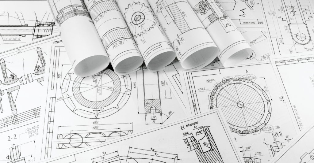
Drawings and images are some of the best ways to show people what you think and how you see things. If you’re an engineer or a machine operator, this is even truer!
The first step is to learn the basics of engineering drawing. In this way, you will be able to explain the purpose of your design for parts made by a CNC machine.
Most people would send their concepts and drawings to clarify their needs better. Not all engineers are skilled at creating simple diagrams.
Unskilled engineers may struggle to comprehend the designs. Poor formatting can affect costs, specifications, and lead times.
In this guide, you will learn about the basics of technical drawing. We also include tips on how you can improve your engineering drawing skills. Through this, you will communicate your thoughts and requirements well. We are helping you save money and time.

Understanding Engineering Drawing!
An engineering drawing will give you a clear idea of what is needed. All of the product’s geometric qualities, both as parts and as a whole, are to be drawn in this way.
This is what this style of drawing is all about. As a result, manufacturers will be able to make parts that meet the needs of each person.
The mechanical drawing includes a description of the production process. This will provide design ideas for the engineering process. You can keep track of parts already installed.
An engineering sketch is more than depicting a process or a product. Components’ forms and sizes are what this is all about.
The descriptions include information about the materials, limitations, acceptable variations, and more. The drawings may differ in shape.
A series of projections that show different angles of the parts are also shown. The main goal of all these things is to meet the needs of the product.
The Fundamental Elements of an Engineering Drawing!
For better parts production, understanding technical drawing basics is a must. A drawing comprises different pieces, each of which has a somewhat different appearance. Understanding engineering drawing’s components will help you interpret it better.
▬ Types of Lines
In an engineering drawing, all the lines are of the same length. One can show hidden and exposed parts edge with a variety of settings.
The continuous line is the most common line type. A drawing line is a common term for this. This element represents an object’s physical limits.
In other words, it’s an object-drawing line type. The line’s thickness can vary. For outer outlines, you use thick lines, while inner contours use thinner ones.
Another type of line used in the mechanical drawing is the hidden line. It helps to show things on the drawing that would otherwise be hidden. A hidden line indicates the length of a step inside a part.
Centerlines state the locations of the holes and how symmetrical a part is. Engineers use extension lines to highlight the area you need to measure. Break lines show a broken view without taking up too much space.
▬ Drawing Views in a Variety of Forms
An engineering sketch has a lot of different perspectives. Each of them has a different job. Make sure that you only add a view that helps you understand the whole design.
▬ Take a Look at Things from an Isometric Point of View
Isometric drawings show parts in three dimensions. Lines that are parallel meet at a 30 degree angle, but lines that are vertical stay vertical. This type of view shows the lines as they are. Optic illusions aren’t always true. This form of perception may be closer to the truth than they are.
▬ The Orthographic View
The best view in an engineering drawing is the orthographic view. It helps to show a 3D object in 2D with the help of an orthographic projection. This ensures that all components can be moved around. The length is also not changed by any means.
▬ Cutout View
Cutouts cut down on the number of different views we can have for a single drawing. It is a good way to make sure that all the dimensions of a cutout are included.
▬ Detail View
This will show the specific parts in a clearer and wider view close-up. You will be able to see essential dimensions even in a small part. It gives you a good picture of how easy it is to read the measurements.
▬ Auxiliary View
Planes that are neither vertical nor horizontal can be depicted in this manner. It does not distort the appearance of inclining surfaces.
▬ Dimensions
Newer CNC machines can read dimensions directly from the line. CAD models may not have all of the necessary information. Tolerances for GD&T and geometric dimensioning may also be required.
Components that are properly sized will last longer and need less maintenance. The measure button allows you to get measurements automatically. However, manual intervention is required to account for engineering tolerances.
▬ Information Blocks
They can be found in the lower-right area of the engineering drawing as small boxes. It includes the name and number of the part, the author’s name and the coating, the quantity, and the scale. Materials costs may also be included in these data blocks. Every part of the assembly must be included.

Improve Your Engineering Drawing Skills with These Crucial Pointers!
Engineering drawing abilities can be improved using the following advice. This method allows manufacturing engineers to easily grasp your component specs.
Tip #1 Only include dimensions of features that can be measured
During CNC machining, it is common for the 3D model to include all necessary dimensions. The threading and inspection dimensions on your mechanical drawing should be minimal.
Tip #2 Add Hole Tapping Requirements to Your Drawing
Thread depth might be difficult to accurately estimate. As a result, you should keep the depth call-out to a minimum at all times.
Tip #3 Call-Outs should be condensed
In views with multiple instances of a feature, only one dimension is required. . The dimension can then be referred to as “#X DIM”. This signifies that the feature has appeared X times in the view. In this view, there are 5 10-38 threaded holes, as shown by the notation “5X 10-38 TAP.”
Tip #4 Instructions for Assembling Critical Components: Communicate Their Intent
Including assembly instructions in your engineering drawing is essential. Remember this when making a large assembly that will be machined together. You can also provide your machinists part numbers to search up. If you’re doing the installation yourself, this is extremely critical.

Tip #5 The importance of part numbers cannot be overstated.
If hardware installation is required, include the provider and part number on the drawing. “press-fit M4 dowel” doesn’t describe the dowel’s substance or length.
Tip #6 When it comes to secondary operations, you don’t need to mention them.
Non-critical operations like polishing and anodizing can be omitted. . Requesting quotations and lead times for these individual tasks is often preferable. You’ll have a better idea of the additional expenses and time involved. If you don’t know what kind of material to use, you can leave it out of the drawing. To avoid misunderstanding on multiple levels, it is important to do this.
Tip #7 Follow these seven simple rules to avoid over-dimensioning or tolerance in your designs:
Only a few features of a component are required for it to function. As a result, you’d like the machinist to pay closer attention to this information. A surplus of dimensions may obscure crucial traits. Tolerances should be applied only to essential aspects.
Tip #8 Tolerance must be within acceptable levels of accuracy
It’s vital to offer your material with adequate tolerance. Do not seek precision beyond standard hand metrology instruments. . The starting measurements utilized by your desired machine shop should thus be researched. Using this information will aid you in making wise choices.

Conclusion
A large part of a machinist’s job involves engineering drawing. Up to 20% of design time is spent on these drawings. So all geometric characteristics of products and their components are captured clearly. Manufacturers will be able to meet your precise requirements this way.
When computer-aided design (CAD) software came out, it made it a lot easier for people to draw. CAD software has a lot of advantages overdrawing by hand. Almost all CNC machines today can read the information right from the files that they use to make things. It also helps to make a cutting plan as needed.
At QBH Technology time and money matter a lot. They are always looking for new ways to save time in the production process. The company has been doing this by automating the reading of 3D models. Their main goal is to produce multiple parts through CNC machining at the fastest possible. Other services they offer include sheet metal, electronic enclosures, and others.
Engineers are only responsible for drawing GD&T and assembly drawings. Producing better parts and products is the main goal of this procedure. With QBH Technology, you can get help on sheet metal fabrication, CNC machining, and others.


