Drawings are the best way to convey your design ideas to a manufacturer. The more detailed a drawing is, the more information it can convey. In the manufacturing sector, technical drawings are standard for sharing design detail. Technical drawings are less about technique and more about strategy.
We have broken down the process of details of technical drawings into simple and easy-to-understand bits. Here is a detailed guide on Technical Drawings

What are Technical Drawings?
Technical drawings are highly detailed diagrams of objects that convey all the necessary information about the construction of the said object.
What are technical drawings used for?
Technical drawings are used in various engineering and architecture-related fields. Technical drawings carry essential information necessary for construction and future repair.

Difference between Technical Drawings and Engineering Drawings
Technical drawing is a broad term that applies to many industries. While engineering drawings are a type of technical drawing.
Engineering drawings are primarily used to detail the geometry information of objects. For complex objects, several drawings are required to give all the necessary information.
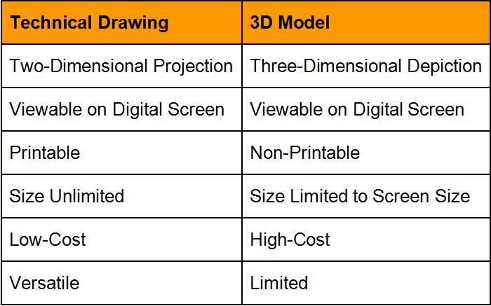
Technical Drawings vs. 3D model
3D models give a full 360° view of the final product. These detailed models are helpful but only to a certain degree. You can only view 3D models on a digital screen running on a reasonably powerful microprocessor. Dimensions cannot be labeled directly onto the 3D model as it would take up a lot of screen real-estate. Instead, you would need to manually click or tap the desired area to find details about its dimensions and tolerances.
Technical drawings present you with detailed views of an object from all six sides. Additionally, technical Drawings can be viewed on a digital screen or printed onto paper.
Basic Components of an Engineering Drawing
When making a technical drawing, you need to be considerate of lines and views. Select the proper lines to convey the correct information. And use a view that shows off the maximum amount of object detail.
Different Types of Lines
The first and foremost important component of a technical drawing is line choice. Here is a brief guide to line thickness and line design. Each type of line corresponds to a different function in a technical drawing.
Continuous Thick Lines
Continuous thick lines are used to draw the outline of an object. This includes the perimeter, edges, and internal cutouts.
Continuous Thin Lines
Continuous thin lines are used for a broader application. They represent everything that isn’t the outline of the object.
Thin lines are used as projection lines, keeping the six orthographic views of the object inline. Since dimension lines run parallel to the main object outline, we use continuous thin lines to distinguish between the two line types visually.
Thick Dashed Lines
Thick dashes are commonly associated with hidden lines. Hidden lines represent cutouts, holes, or sections that lie behind a view.
Chain Thin Lines
Chain lines represent the center lines, symmetry lines, and trajectory lines. Center lines are the most common use of chain lines. Two chain lines intersect at the center of a hole or cutout.
Zig-Zag Lines
Zig-Zag lines shorten long object outlines to fit within a specific area. The technical term for shorting long lines is Break Lines.
Here are some additional line types that can add further detail to your technical drawing.


Types of Views
For technical drawings, Views refer to the depiction of objects in the 2D plane. There are various methods of depicting your object design, but the following are the most popular ones.
1.Isometric View
Isometric view is a method of depicting three-dimensional objects in a two-dimensional space. An isometric view is essentially the same as a photo of the object. The angle of the photo here is such that you can see at least three sides of the object.
Isometric views are most used for simple objects with very little complexity in design.

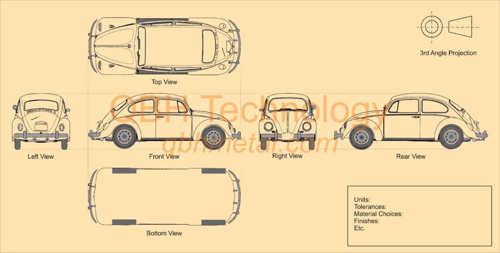
2.Orthographic View
An orthographic view is the most common and helpful depiction of a drawing. Basically, you take an image and break it down into its six sides. This allows you to draw each side of the object in detail and showcase information from all sides.
An orthographic view can be further divided into two subcategories.
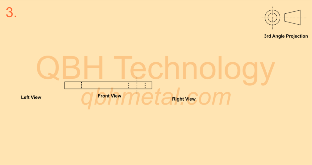
a.1st Person Projection
b.3rd Person Projection
Both methods are similar, and the only difference is in the placement of the side and top view in the technical drawing.

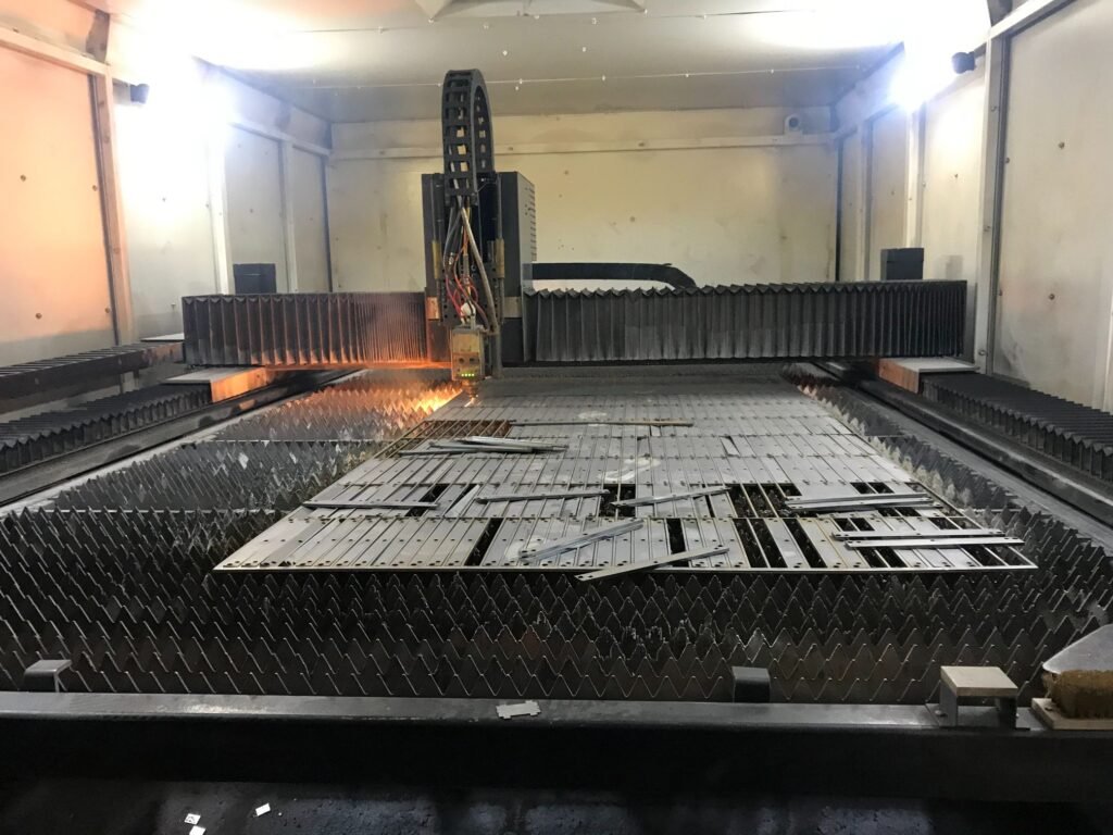
3.Flat Pattern
Objects that require sheet metal fabrication can be drawn as flat patterns that can be stamped out of metal sheets. These flat patterns can then be bent into the appropriate shapes.
This method is not essential since it is the same as orthographic projection but with different placements of side views.

4.Section View
Section view adds another diagram to the drawing, showing the object’s internals if it was cut in half (sectioned).

5.Cutout View
Same as section view, but instead of an entirely bisected view, the diagrams selective shows cutout sections of some areas.

6.Detailed View
The detailed view uses an additional diagram to depict a zoomed-in view of the object.

How to draw a Technical Drawing?
Technical drawings have existed since the times of the earliest civilization. Ancient Chinese and Egyptians made technical drawings using ink and rice paper (or papyrus). Modern-day technical drawings rely on CAD (Computer-Aided Design) software to achieve higher precision and technical refinement.
However, hand-drawn technical drawings are still popular among many manufacturers. They are a quick and easy way to generate a draft without a computer.
Hand Drawn Method
You can draw a basic technical drawing using nothing more than a pencil and a piece of paper. The paper should be A1 size or larger for accurate and detailed drawings. Outline the object using thicker lines and use thinner lines for projection lines and minor details.
CAD Software Method
CAD software allows you to input exact dimensions into the computer to draw shapes. You can draw lines at every angle possible and easily copy lines or entire drawings. The most significant advantage of CAD drawings is that they can be exported into different file types.
The following are common file types that can be created using CAD software.
- PDF – For easy sharing and printing.
- STL – For Slicing and 3D printing.
- G-code – For CNC machining.
Steps for making a Technical Drawings
The following are the basic steps involved in making a technical drawing. These steps can be applied to both hand-drawn and CAD methods.
Step 1
Carefully look at your object and determine a “Front View.” The front view is the center of your drawing, and all other sides will be designated right, left, top, or bottom.

Step 2
Now using either 1st Angle Projection or 3rd Angle Projection, determine the other sides of your object.

Step 3
Using the proper lines, draw the Front View of your object. Use hidden lines for any details that are obscured by parts.
Step 4
Using projection lines, define the general position of the side views relative to the Front View. Then draw the Left or Right View of the object. Your side views should have the same vertical height as your Front View.

Step 5
Now, using the same technique as before, draw the Bottom & Top Views of your object. Your top and bottom views should have the same horizontal height as your Front View.

Step 6
Draw the Rear View if necessary. If your Front View and Rear View are identical, you can skip this step.

Step 7
Go through your drawing once, and look for any missing details. If a hole is visible in the Front View, you need to show it in the side videos as Thick Dotted lines.

Step 8
Label all the dimensions in your drawings. Reference the dimension units (inches or mm) in the top or bottom right corner of the drawing. Any additional details regarding the object should be mentioned here as well.

Step 9
If you drew the technical drawing, save it on your computer in the desired file type.
Manufacturing Using Technical or Engineering Drawings
Now that you have mastered the art of technical drawings, it is time to put your skills into practice. Technical drawings can be used with most manufacturing techniques with little to no difficulty.
But some manufacturing processes will benefit from additional tweaks to your technical designs.
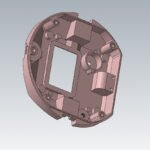
CNC Machining
Manufacturing using CNC machines is slightly different from other methods. CNC machines can use multiple cutting tools on a single object. And each tool will come with different internal tolerance.
- Properly mention the different tolerances for different sections of the object.
- Hole and cavity details should include information about countersinks and variable diameter.
- If your design includes thread sections, use standard thread specifications.
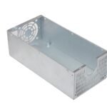
Sheet Metal Fabrication
As discussed previously, you can use both orthographic and flat pattern drawings for sheet metal fabrication. Both convey the same amount of information, and the only difference is visual depiction. Either way, you need to include some additional information.
- Mention the desired gauge (thickness standard) of metal.
- Properly disclose the welding locations.
- Dimensions should allow for bending and welding tolerances.
- Mention grain bend direction if possible. Bending parallel to the grain requires less strength but results in a weaker being and vice versa.

Aluminum Extrusion
Extrusion techniques are generally suited for simpler designs. Most technical drawings need minimal alteration to be compatible with the extrusion process.
- Mention the desired stock (billet thickness) size.
- Grain direction is crucial for extruded metal parts.
- Holes need to be adequately detailed in the technical drawings.

Conclusion
Technical drawing may seem complex and challenging, but the process becomes much simpler once you know the basics. When making technical drawings, make sure to include all the necessary information. Dimensions and tolerances are crucial bits of information, but material choices and finishing options are also appreciated. Keep your drawings as clutter-free as possible, evenly space your side views and be mindful of hidden lines.
Your technical drawings are only as good as the manufacturer’s skills. For high-quality metal parts manufacturing services, we recommend checking out QBH Technology. We offer all sorts of Sheet Metal , CNC Machining, and Stamped Metal fabrication services.
We offer competitive prices and flexible minimum order quantities. Additionally, QBH respects customers’ confidentiality and keeps your private designs safe. To achieve your product goals and get best in class services, Contact Us Now!