QBH Technology

分类
Blog

Metal Plating Finishes:Which Metal Plating Finish Do You Need?

Metal plating is a complex process. To get the desired quality and results, you must choose the right technique and company. for the metal plating finish. You can find many metal plating and surface finishing methods and choose the most suitable for your production.

The primary purpose of surface finishes is to improve the aesthetic of prototyping and products and make better functionality. Selecting the metal plating is much complex, and we are giving you some helpful tips to choose the best plate finish, guaranteeing improved finish quality.

  • The bright Acid Tin Plating process uses to plate metals and provide solderability, electrical conductivity, and heat resistance to the material.
  • Bright Nickel Plating can plate copper, steel, iron, brass, and this method provides corrosion protection.
  • Chrome plating uses for the plating of plastics and provides surface hardness and corrosion resistance.
  • If you want to plate ferrous metal, you must go for the Cold Chemical Blacking process, which provides a lubricative layer and reduces the light glare.
  • If you want to make metals tough, non-magnetic, and ductile, you must need copper electroplating. To give the copper, iron, and grass a good conductivity, electroless Nickel Plating is the best choice.
  • If you are looking for the plating of a metal having a conductive surface, you need to do Gold Plating to your metal. It will provide a conductive layer and resistance to corrosion.

So, before the plating, you must have complete information about the plating techniques and their benefit. Now let’s see what some main advantages of metal plate finishes are and how to choose them.

What are Metal Plate Finishes and Their Advantages/ Benefits?

It is a post-production method of metal plating in which we coat a surface of a metallic part of a workpiece. The purpose and role of the coating is to improve the product quality, polishing, and cleaning. Metal plate finishes can be a chemical, mechanical or physical process, and it is often used to describe the last phase of fabrication. This phase can be of non-metallic products or metallic products. There are many processes involved in the metal finishes process, and each process has its unique and specific advantages. Some common advantages /benefits of metal plate finishes are:

  1. You can use metal surface finishes to improve paint adhesion.
  2. It can prove helpful to reduce the friction of a surface.
  3. It can serve as an essential coat to increase paint adhesion and make an electrically conductive surface.
  4. It can change the conductibility ad conductivity of a material.
  5. For improving corrosion resistance, heat resistance and parts wearability, you can apply metal plate finishes.
  6. Metal plate finishes protect against radiation and also boost solderability.
  7. Metal surface finishes are used for cleaning and removing surface defects.

Standard Industrial Plating Types

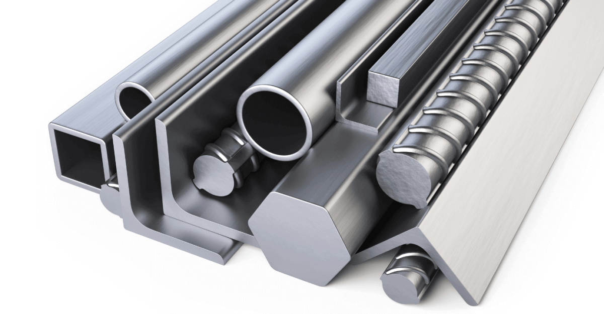
You can classify electroplating into types of metal used in the coating. A wide array of metals is included in standard metals such as chromium, nickel, tin, gold, zinc, copper and various alloys. We are discussing some of the standard industrial metals types as under:

1: Chrome Plating

The primary function of chrome plating is to improve the aesthetics and corrosion resistance of a material. Chrome plating involves chromic acid and trivalent chromium to manufacture an overlay on the parts, and it also increases the hardness of the material on which you apply chrome plating. It makes parts suitable for various industrial applications.

2: Nickel Plating

Nickel is a lustrous, sturdy base coat mainly used for silver and gold. It hardens the surface and enhances the wear resistance. Nickel plating uses for coating and painting household accessories such as showers, doorknobs, and fixtures, and it is popular because of its effectiveness in electroless plating.

It can improve the wear resistance and aesthetic of parts and also apply as underlying chromium plating. You can use nickel plating for a wide range of materials, but it mostly recommends copper and aluminium parts.

3: Tin Plating

Tin plating refers to tinning, and it is a cost-effective process to achieve a semi-bright, matte and bright appearance. Tin is easily accessible, a soft, malleable metal, and becomes less costly when we use it with other metals.
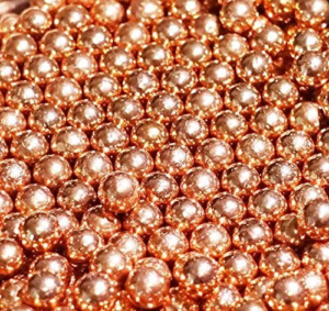
4: Copper Plating

Copper is a good conductor of electricity, and for high conductivity and cost-effective application, copper plating considers one of the best choices. It serves as the primary coating pretreatment for plated finishes and prefers manufacturing semiconductors, circuit boards, electronics, and many other electric components. Copper plating is known because of its high plating efficiency, high conductivity, low material cost, and improved adhesion.

5: Gold Plating

Gold plating is known due to resistance to oxidation and high electrical conductivity. Gold plating can be a good choice when you need to impart these characteristics to copper and silver. The application of gold plating can improve electrical parts conductivity, such as electrical connectors and components. Gold has superior value for the electroplating option and has glamour and glittering features.

6: Zinc Plating

Zinc is readily available, and this availability makes zinc plating a cost-effective option for metal plate finishes. The main benefits of zinc plating are excellent corrosion protection, and the uses of zinc are on small metallic parts like screws, bolts and nuts.

Different Metal Plating Techniques

Several techniques are used for metal plating. Following are the most widely used techniques for metal plating.

 1: Electroplating Metal Plating Finishes

Metal Plating

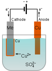
Electroplating is considered the most common technique of metal plating. It is an electrolytic process. In this process, the electric current is passed through a chemical solution. It can dissolve the ions. Due to the electric current, the positively charged ions move toward the cathode, and the negatively charged ions move toward the anode. As a result, the plated material is evenly and smoothly coated. Electroplating significantly improves the chemical, mechanical and physical properties of the plated material.

2: Electroless Metal Plating Finishes

Metal Plating

Electroless metal plating doesn’t require any electric current for plating. Electroless plating uses the induction process instead of electric current, and it involves a chemical reaction resulting in the induction of the metal atom reduction. As a result, the metal particles solutions transforms into a metal solid after mixing with a reducing agent. In the end, the material is coated with solid plating metal. There is no plating bath and electricity in this process, so this technique is more cost-effective.

Moreover, electroless plating can perform on a variety of materials. Electroless plating is a slow process and does the thinner plating. This technique is more suitable for nickel plating. It provides more protection than the conductivity and solderability of the material.

3: Immersion Metal Plating Finishes

Metal Plating

In immersion plating, the metal dips into a solution containing metal ions. The noble metal ions are generally more stable. This technique causes the natural pull of the metal ions from the initial metal, which is displaced by the noble metal ions. A thin layer of noble metal ions is formed on the metal.

It is a much slower process as compared to other techniques. A thin plating coverage is formed as a result of the immersion technique.

 Application of Metal Plating Finishes

Metal plating finish provides a lot of applications. Following are some uses of the metal plating finish.

1- Improved Appearance

Metal plating finish is widely used to improve the appearance of the metals. The surface of metals may lose its lustrous appearance with time. Metal plating finish gives a new look to the metals.

 2- Corrosion Resistance

Most metals and machinery may become damaged due to rust, so they require a metal plating finish. The metal plating acts as corrosion-resistant by providing an effective barrier against rust.

3- Improve Electrical Conductivity

Metal plating finish uses to improve the electrical conductivity of most of the surfaces. Most of the non-conductive surfaces require the passage of electric current. So, the metal plating finish is the best option for them to make them electrically conductive.

 4- Heat-Resistant

Most of the equipment is highly sensitive to extreme temperatures. They may become damaged after exposure to heat. The metal plating finish of such equipment protects them from damage due to heat exposure.

 5- Restoring a Polished Surface

Most of the metal and surfaces may lose their polish and look unattractive. Metal plating finish helps in restoring the polished surface and makes them more attractive and good-looking.

Conclusion

Metal plate finishing is an easy process and can improve the functionality and aesthetic of the material. A wide range of materials can use for metal plate finishes. Therefore select an experienced company with a low budget is essential to work.

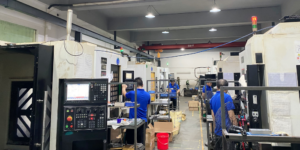
Whether you are looking for a CNC machining service or sheet metal fabrication, QBH technology is your best choice. We deliver efficient and effective sheet metal and CNC fabrication. Delivering high-quality results and saving customers time and money is our top priority.

Contact us today and get a great experience. QBH technology will be your metal finishing expert that offers perfect services at cost-effective budgets.

分类
Blog

What are Precision, Tolerances and CNC Machining Accuracy?

Introduction

There are three pillars of every high-quality CNC yield – “Precision, Accuracy, and Tolerance.” Most CNC machine experts talk endlessly about delivering the highest precision, accuracy, and tolerance through their ‘state-of-the-art’ technologies. But it’s nothing other than a marketing gimmick. Frankly speaking, behind every high-quality CNC machining service is sound knowledge and understanding of machining fundamentals and concepts.

To help you have a firm grasp over CNC machining, we will get down to the nitty-gritty of CNC milling machine accuracy, tolerance, and precision. The information in the post will help you better define your product design requirements and manufacture without feeling overwhelmed. Let’s get started!

CNC machining

What is accuracy

Accuracy is keeping the degree of conformance to a known standard or value. Seems confusing? Let us understand it in depth. A highly accurate CNC machine, set to cut a piece of metal 100mm long, should cut the metal to exactly 100mm. In other words, there should be no error. The more accurate the CNC machine will be, the easier it will be to get exactly 100mm.

The term ‘accuracy’ can be defined as follows:

“The degree to which a measurement or movement in space conforms to a systematic standard or one of its derivatives – typically the millimeter or micron for metric measurements.”

However, accuracy isn’t inherent to the CNC machine. You will have to understand and learn how to use the machine well. After all, some machines are more accurate, and some are less. But, to achieve the best result, you will have to set up and run the machine in a certain way. So, how should you improve your CNC machine accuracy? Here are some of the best practices you can employ and achieve accurate product design.

1.Know the spindle

It is crucial to know the spindle’s behavior. You might want to treat the tool-tip position as static, but varying speeds create different temperatures and centrifugal forces within the spindle. As a result, the spindle responds and fails to hold tighter tolerances. We suggest you conduct adequate experimentation to identify the tool-tip position. This helps apply tool offsets to make appropriate corrections.

2.Identify potential error sources

Although inspection happens after the machining process is over, we suggest you measure and inspect first to identify the sources of errors. This gives you a chance to correct the measurements before machining. What can be the potential sources of error? A machining center (three-axis) has 21 potential sources of inaccuracy. Simply identifying the potential error sources will help reduce the need for gaging.

3.Don’t ignore the drawbar

The drawbar delivers the holding force required to keep the spindle in place. Therefore, one should inspect the drawbar routinely. Reviewing the drawbar condition once every month keeps the machine’s accuracy in check. A weak drawbar will not only increase the probability of error but also significantly reduce the tool life. One should expect the drawbar repair and approach it periodically.

4.Reduce the chatter

A loose setup and tooling often result in chatter. Chatter can be put in check using diagnostic tools. Such tools overcome chatter by finding a spindle speed at which the rate of cutting edge impacts harmonizes with the system’s natural frequency. You should also engage in test cutting to find the ideal spindle speeds. This will help achieve a quieter cut and better accuracy. It also helps achieve a higher metal removal rate.

5.Check performance with a reference

You can use a known reference object inside the machining zone to inspect the CNC machine’s performance. Make sure the reference object is made from the same material and has similar geometry. The reference object will allow you to capture any measurement error and calculate the difference between the known value of a reference dimension and the measured value of that same dimension. You can use the difference as an offset and achieve better accuracy. 

CNC Machining

What is precision?

When it comes to using CAD software to design a product, the result is often a precise one. It’s because the software is designed to reliably produce/repeat any design feature. Such software reduces labor and saves time. However, things change dramatically once you take the drawing to a factory.

Precision during CNC machining refers to the machine’s ability to repeat an action every time without producing a random error. In other words, precision machining involves controlling the process without deviating from the process or measurement. Accuracy and precision are used interchangeably. But, both are quite different. Let’s discuss how we can achieve precision in CNC machining.

1.Use good CNC programming skills

The most basic task in CNC machining is CNC programming. You will need an experienced programmer that can write a flexible intrinsic program while reducing the cumulative error of the CNC system. The programmer should be able to leverage the relationship between the main program and subroutines. This helps improve processing efficiency and consistency.

2.Adjust the processing system

One should adjust the blade extension according to the workpiece material and then perform a trial cutting. Machining experts often use this method for single-piece small batch production. It will be easier to achieve precision if you adjust the relative positions of the machine tool, workpiece, and fixture. 

3.Reduce the measurement errors

Measurement errors will increase the probability of a bad product design. Therefore, you should aim to prove the machining accuracy of the box support hole and spindle shaft journal. Routinely measure and adjust the radial runout range of the corresponding part to reduce measurement errors.

4.Measure and adjust parts with bearing

CNC machining requires the parts with bearing to be accurate. The rotation accuracy of the bearing is crucial for the CNC machine to perform correctly. Therefore, you should strive to improve the rotation accuracy by selecting cylindrical roller bearings, multi-oil wedge bearings, and hydrostatic bearings.

5.Keep machining tools in good condition

Make sure you keep all the machining tools in prime shape and condition. Routinely indulge in tool regrinding as it helps extend the tools’ life. You can also purchase special cutting oil to maintain sufficient lubrication in the CNC machine. Most importantly, choose the correct lathe tools during the machining process.

6.Reduce thermal error

The thermal error occurs due to the thermal deformation of the processing system. Such errors depend on various factors like cutting speed, feed, machining time, and environmental temperature. Focusing on the factors and tips mentioned above will help improve precision during CNC machining.

What is the difference between accuracy and precision?

Now that we have discussed accuracy and precision in detail, can you tell the difference between the two? Do the differences even matter if both accuracy and precision are used interchangeably? Let’s find out.

Let’s assume we are throwing darts to hit the bullseye on a target practice chart. Accuracy, in this situation, will mean ‘how close’ the dart is to the center of the chart (10 points). Let’s say you hit to achieve 9 points. This means you were 90 percent accurate with your shot. 

Now, you decided to hit a seven-pointer thrice. If you succeed, you will be 70 percent accurate. However, you’d have achieved more precision. In other words, precision refers to the repeatability of a certain outcome.

Let’s understand precision and accuracy in terms of manufacturing. Let’s say you need to make a 50mm x 50mm x 50mm cavity in a copper workpiece. A highly accurate CNC machine will deliver a piece of exactly 50mm x 50mm x 50mm measurement. A highly precise CNC machine will deliver this exact same cut for multiple units.

CNC machining

What is tolerance?

The last measurement concept you need to learn is tolerance. CNC machining comes with an allowable deviation that is accompanied by a value. You will find CNC machine shops claiming their machining tool can achieve a tolerance of some value. This is important to note since the machining operation might introduce a deviation of up to 0.05mm in the units. 

For example, let’s say you need to create a 10mm hole in a copper workpiece. A CNC machine with a tolerance of 0.05mm might create a hole with a diameter ranging between 9.95mm and 10.05mm. Tolerance is a crucial factor that can impact your design’s functionality. Therefore, we suggest you learn how to achieve small tolerances in a design.

Firstly, you should know that not all parts require tight tolerances. We suggest you consider the function of your part before determining the degree of accuracy required. Parts that don’t interact with other working parts don’t require high accuracy. Achieving tight tolerance is a costly affair. So, we wouldn’t recommend it for parts that don’t need such high accuracy.

Secondly, one should only go for reputable CNC machinists. Only an experienced manufacturing expert will understand your goals and specifications. Subsequently, the expert will share the best tolerances for your project. However, CNC machining services will automatically work with the standard (±0.005 inches) tolerance. Such small deviations are not noticeable to the naked eye.

1.Use quality CNC machines

You should not compromise the quality of CNC machines or workshops. It is virtually impossible to achieve the desired tolerance in a trembling workshop. Check the CNC machines. If you work on a machine with a tolerance of ±0.02mm, how can you guarantee a ±0.01mm tolerance? A workman is as good as his tools. 

2.Set the right temperature

The workshop temperature also matters when making precise parts. Temperatures within a workshop can vary by more than 10 degrees between day and night. Therefore, you can’t expect a consistent tolerance while working on the metal with such significant temperature variation. Make sure you work on the project in a workshop with air conditioning. 

3.Get the tool holder balance right

Tool holders in the CNC machine should have a dynamic balance. Unbalance will eliminate accurate machining. Without balance, the CNC machine will experience misalignment, asymmetrical rotor design, concentricity errors, and other errors resulting in less accurate parts. You should use a professional balancing service if the holders aren’t designed for easy adjustments. 

4.Use correct sharp cutting tools

We suggest you use high-quality and sharp cutting tools for parts that require high tolerances. Dull cutting tools will wear out your CNC machine and reduce the part’s accuracy and precision. This is because the dull tool has a larger radius, making it difficult to make shallow cuts. Take good care of the tools and keep them in proper condition. 

5.Performance on-machine inspection

Inspect the finished parts as part of quality control. This helps guarantee tight tolerances. We recommend using an on-machine inspection system that keeps the machine’s accuracy in check. Renishaw inspection systems are one of the best on-machine inspection systems available in the market. These provide automatic offset correction.

Keep reading!

There you have it. This extensive guide focused on breaking down concepts of accuracy, precision, and tolerance with respect to CNC machining. To summarize what you have just read, ‘accuracy’ is achieving a design that is close to the standard; ‘precision’ is achieving accuracy over and over again; ‘tolerance’ is keeping variability to a small and acceptable degree. We hope that now you can define your product design requirements to any CNC machining expert without confusion. Did you find this post helpful? Let us know in the comments. Also, don’t forget to check out other informative posts on the blog!

分类
Blog

Hands-on Ideas for Speeding up Manufacturing Metal Parts

While selecting a manufacturing process for metal parts, you need to determine which can complete your project in less time. You cannot pick the wrong one as it will alter the functionality of the components. In this article, we have covered the basic principles of each manufacturing process, their production speed, and the materials used. So, you can choose the right one.

How to Select the Fastest Manufacturing Process for Metal Parts?

Faster manufacturing of metal parts reduces time-to-market and increases profits. Even if you produce parts with on-demand manufacturing, you are entitled to choose the speed of your production process. Here we have highlighted the most common high-speed production processes:

Sheet Metal Fabrication

Fabrication is forming components from raw materials by combining two or more processes. 

Sheet Metal Fabrication is a subtractive manufacturing process that involves forming parts from flat metal sheets. Design the parts in 3D CAD software and connect them with various manufacturing tools through written coding. You can cut, bend, stretch, or assemble the sheets into different shapes by combining all manufacturing processes. 

Speed: You’ll find that Sheet Metal Fabrication requires various tools and machinery for each individual process. Hence, the short-run production and prototyping speed are lower than CNC Machining, which provides all-in-one processes.

manufacturing

Best for Materials: 

  • Zinc.
  • Aluminum. 
  • Copper. 
  • Steel.
  • Stainless Steel. 

These materials come in gauges ranging from 0.015 to 0.635 centimeters.

You can use this process for producing: 

  • Low-cost end-use applications like device panels, enclosures, brackets, boxes, cases, and chassis.
  • Lightweight applications.
  • Thin-walled components that are not possible or cost-effective to be built with CNC Machining.
  • Projects which need complex designs, repeating shapes, and patterns.

CNC Machining

CNC stands for Computer Numerical Control, a method of automating the motion of machine tools through pre-programmed software. 

CNC Machining is a computerized manufacturing process where the software controls the movement of complex machinery. The tools cut, shape, and create different metal parts through subtractive manufacturing, a controlled material removal process. 

CNC Machining provides a fast manufacturing process for prototyping and short-run productions, where one production factor is fixed. Also, you won’t need any extra tools as the 5-axis machine reduces the time for multiple setups.

Speed: CNC machines are faster than manual ones, with a feed rate that can exceed 2,300 inches per minute (ipm). 

A feed rate refers to the speed the tool advances through the workpiece and is usually measured in inches per minute.

manufacturing

Best for Materials: 

  • Brass. 
  • Aluminum.
  • Copper.
  • Stainless Steel.
  • Carbon steel.

You can use this process for producing:

  • High-quality materials.
  • Projects with tight tolerances meaning they have strict design parameters and require more precision and accuracy.
  • On a scale of up to 10,000 parts.
  • Projects that require custom finishes.

Metal Injection Molding (MIM)

Metal Injection Molding is a process that involves injecting raw powdered metal with measured polymer binders to make feedstock. 

Binders shape and hold together the metal particles until the onset of the molding process. They are removed before sintering, a method to form and compact a solid mass of material through heat and pressure without liquefying it.

The feedstock mixture is solidified and further molded to form metal components with desired strength properties. 

Speed: Metal Injection Molding is a two-step manufacturing process, and molding takes time. So, the short-run production and prototyping speed might be less. But once the metal injection shots are completed, you can instantly produce a high volume of metal parts.

Best for Materials: 

  • Steel.
  • Stainless Steel.
  • Tungsten Alloys.
  • Cemented Carbides.
  • Cobalt-Chromium.
  • Copper.

You can use this process for producing:

  • Small parts in high volume.
  • Manufacturing complicated shapes that are not cost-effective with other processes.
  • Finely detailed textures, engravings, profiled holes, and net shape features such as internal and external threads. 
  • Medical devices.

Metal 3D Printing

Metal 3D printing is an additive manufacturing process where you can create a metal design using 3D “CAD” software. The digital file is transmitted to the machine used for building components.

The process works by spreading a thin layer of metal powder and fusing the particles with the help of a laser. The process is repeated until the layers form a metal part. 

Speed: It is a fast manufacturing process with a short setup time. However,  it has concise production runs so that you can produce only ten units or less. 

Best for Materials: 

  • Super Alloys.
  • Aluminum.
  • Tool Steel.
  • Stainless Steel.
  • Silicone-Carbide. 

You can use this process for producing: 

  • Parts with complex geometries that are otherwise impossible.
  • Replacement parts for legacy systems.
  • Low-volume prototypes for functional testing.

There are many choices in Metal 3D Printing, but here we are mentioning only the renowned and most used ones:

Selective Laser Melting (SLM)

Selective Laser Melting, as the name suggests, Selective Laser Melting selects metal powder with a single melting temperature to melt it completely. 

Best for Materials: 

  • Only selective metals.
  • Stainless steel. 
  • Tool Steel.
  • Titanium.
  • Cobalt chrome.
  • Aluminum.

You can use this process for producing: 

  • Metal equipment as a whole rather than components.

Direct Metal Laser Sintering (DMLS)

The Direct Metal Laser Sintering process uses a metal powder with variable melting points to fuse the particles at elevated temperatures. 

Best for Materials: 

  • Almost all alloys.

You can use this process for producing: 

Aerospace and automotive parts that operate under high stress.

manufacturing

Principles of Design for Manufacturability (DFM) for Metal Parts 

Design for Manufacturability works on five fundamental principles that you need to consider while designing your project. Following them will produce quality metal parts in a short time. Here they are:

1.Process

Choose the proper manufacturing process regarding the materials used, the surface complexity, and the required volume of parts. In some cases, the metal components don’t require complex manufacturing. So, choose wisely.

2.Design

Designing your project is vital. Don’t forget to discuss the design with your manufacturer. Only they can ensure that it conforms to the principles of the manufacturing process you’ve chosen. Your plan will include specifications, tolerances, thickness, and texture. But don’t specify tight tolerances where they are not needed.

3.Materials

It is essential to select suitable material for your project. Consider the material properties and choose one that is easy to process. For instance, CNC machines can cut aluminum quicker than steel. Contact your manufacturer as they may have existing materials so you can secure them at lower pricing. 

4.Environment

Your project won’t matter if it won’t be operational under normal conditions. So, be sure to design it to withstand the environment in which it will be utilized. 

5.Compliance

Your project should comply with industry and third-party safety and quality standards. Only give your project to a manufacturer who can provide quality assurance.

manufacturing

Conclusion

Quick manufacturing processes that can shorten production time for metal components are the need of the hour. After reading the article, we hope that you’ll now be able to choose materials and a manufacturing process suitable to your project needs. But be sure to keep your design free of ambiguities. Moreover, be clear about your objective to your manufacturer. 

Having said that, at QBH Technology, we take pride in producing custom metal parts at competitive rates. We have decades of experience providing manufacturing services for CNC Machining, Laser cutting, server rack & cabinet, and much more. Our expertise includes CNC Machining and Metal Sheet Fabrication. We ensure to manufacture your product with great precision and accuracy in a short duration. Contact us for a free quote!

分类
Blog

How to Design a Waterproof Enclosure in Manufacturing?

Introduction

Water is life. But, it makes life difficult for products that aren’t waterproof. Manufacturers are always in search of waterproof enclosures that render their products waterproof and rugged. What does designing waterproof enclosures involve? In this post, we will dive into the world of product design to learn how to design waterproof enclosures for manufacturing purposes. We will understand the different waterproof grading/rating systems, the required parts, and the material best suited to design waterproof enclosures. So, let’s cut to the chase and jump into the content!

What are the different waterproof grade rating systems?

  • Ingress Protection (IP)

Ingress Protection or International Protection (IP) is a marking system that evaluates how well a product’s sealing protects it from water and other solid objects. Mostly used to define the waterproofing ability of electronic products, IP rating is mentioned on the device using IPxx inscription. In this, IP stands for Ingress Protection, and ‘xx’ is the two-digit number that defines the waterproofing ability. The first digit in the number shows protection against physical objects, while the second digital shows protection against liquids. The higher the IP rating of a product, the better is its waterproof enclosure. 

  • NEMA rating system

National Electrical Manufacturer Association or NEMA is another popular rating system that is mainly used for industrial products. It is different from IP rating as it focuses on protecting a product from highly intrusive parameters like ice, corrosives, oil, and more. Not just that, it takes into consideration factors like environment (indoor or outdoor), exposure to corrosive agents, and frequency of the product getting in contact with water. NEMA rating is different from indoor and outdoor use. For indoor usage, the industrial product is rated from 1 to 13.

The level of protection improves as the rating increases. Products designed for outdoor use ratings like NEMA 3, 3R, and 3S. NEMA 4 is the rating used exclusively for industrial products used in high-pressure water conditions.

  • MIL-SPEC rating system

Lastly, we have the MIL-SPEC rating system developed around WWII. The US Department of Defense uses the MIL-SPEC rating system to test a product’s manufacturing, maintenance, materials, and design. It takes factors like humidity, rain, altitude, fungus, temperature, salt fog, dust, san, vibration, transport, leakage, acceleration, and explosive atmosphere into consideration. The best thing about this rating system is that it is always evolving. Hence industries following the MIL-SPEC rating system always end up producing better products. 

waterproof enclosure

How to design waterproof enclosure seals?

  • Gasket sealant

Industrial products involving mechanical joints gain strength when an adhesive glue, paste, or spray is used to join them together. It significantly improves the waterproofing ability of the enclosure and keeps it from any mechanical breakdown when parts come in contact.

A gasket is helpful, especially when making complex face-to-face seals that involve multiple cavities. We highly recommend you consider factors like compressions, tolerances, and thickness of the joints before using a gasket to connect them. Thankfully, you don’t have to worry about standards, as gaskets can be easily customized.

  • Static O-Ring seals

O-rings are incredibly successful in producing water seal designs and repairing similar products. Although they have one shape, O-rings come in different sizes, which makes them universally accepted. Every O-ring has two numbers denoting the inside- and the outside-diameter.

Static O-rings are perfect for products that are circular in shape. These work best when the mating gland parts do not move relatively. This makes sure that there is no movement in the sealing surface. As a result, status O-rings make low maintenance sealants. These require less lubrication as well.

  • Dynamic O-Ring seals

Another important O-ring type is the dynamic O-ring. Industrial products with mating gland parts that move make the best use case for dynamic O-rings. Since the parts are moving, dynamic O-ring requires more maintenance and lubrication. Not just that, the sealant should be tougher than static O-rings, and the mating gland parts should have a surface finish. An abrasive surface can lead to wear and tear in the sealant.

  • Button

Does your industrial product require interfacing? Buttons will give your product the best seal. These are highly useful in sealing directional pads, triggers, panel switches, and other products, as buttons can be made from different materials. Buttons are ideal for both light and heavy-duty designs. Molded rubber buttons can seal products that require a low-pressure waterproof design. Buttons made from harder materials work best for heavy-duty waterproof button design. Many waterproof enclosures use both O-Ring and button seals. However, you should use multiple seals with caution as these are prone to seal failure.

How to choose a suitable material for waterproof enclosures?

Material selection is core to making a solid waterproof enclosure design. Selecting the right material requires one to understand the important factors involved. In this section, we will help you get acquainted with factors that will help you make the right choice.

  • Figure out the stages of product development

The stages of development your product will undergo matter when choosing a waterproof enclosure material. For instance, product development usually starts with prototyping the actual product. Since it is a prototype development stage, you wouldn’t want to go all the way and use high-quality material. Instead, you will go for low-level material to capture the right fit and function. Once you identify the errors in the prototype, you can go ahead and use original materials to develop the product. 

  • Refer to the use and design guide

The design guide plays a crucial role in determining the type of materials required in manufacturing waterproof enclosures. Manufacturers receive a design guide which is nothing but documentation for how the product is to be made. The guide is quite informative as it helps manufacturers determine the product dimensions, materials required, and the procedure suitable to manufacture the product. 

  • Environment where the product will be used

When choosing the material, we will also have to consider the environment where the industrial product will function. You should know if the waterproof enclosure material suits indoor or outdoor usage. The material selection will play a huge role in determining the durability of the product.

waterproof enclosure

Which material is best to design waterproof enclosures?

So, which material is suitable for designing waterproof enclosures? Plastics and metal alloys are quite popular across waterproof enclosures. Let’s discuss both in detail.

  • Plastics

Plastics make a perfect choice of material where strength isn’t an issue. It is a versatile choice of material since plastics are easy to mold, corrosion-free, and replaceable. However, superior waterproof enclosure designs usually ditch plastics and go for metal and alloys.

  • Metals and alloys

If you are looking for a high-quality, robust, and durable waterproof enclosure, you must consider the following metals and alloys –

  • Steel

Steel is the preferred metal alloy, especially when you need to install a waterproof enclosure in an environment prone to corrosion. Also, steel makes a perfect waterproof enclosure material since it is strong, robust, and is scratch-resistant. However, you will not want to use steel in a product used primarily in corrosion-causing agents or the environment. 

  • Stainless Steel

Stainless steel delivers qualities like steel, but it goes an extra mile to ensure the product functions in a high-corrosion environment. It makes one of the most durable waterproof enclosures that can outlast even the most challenging conditions.

  • Aluminum

Aluminum is a corrosion-resistant material that provides waterproof enclosure stability in saltwater. It makes an easier choice for manufacturers that are looking for enclosures with better physical attributes. Moreover, aluminum is lightweight. However, we will not recommend you use it in an alkaline environment as it readily reacts in such conditions.

Waterproof Enclosure

Conclusion

Now that you have a basic idea of what it takes to design a waterproof enclosure, it will be easier to make firm decisions regarding the various factors involved in the process. You are in the best position to determine what you need to design a waterproof enclosure for an industrial product. We highly recommend you plan the interfaces well in advance, so you know the size of O-rings and button styles suitable for your project. Did you find this post helpful? Let us know in the comments. Also, don’t forget to check out other informative posts on the blog!

分类
Blog

An Overview of Heat Treatment Processes & Benefits

Introduction

Metals require heat to get in the desired shape, become harder, and be less brittle. Since modern machining thrives on sophistication and precision, it is crucial that we heat treat the metals appropriately to help them gain a permanent set of properties. Hardness, strength, machinability, elasticity, formability, and other critical properties change when metals undergo heat treatment. When heat-treated properly, metallurgists can harness the remarkable chemical and physical properties of metals and prepare them well for machining. Let’s understand the heat treatment of metals in more detail, shall we?

What is heat treatment?

Heat treatment is a simple process in which the metal or alloy is heated to a certain temperature and cooled. The heating and cooling of the metal changes the microstructure of the metal and brings out the desired chemical and physical properties required for a project. While the very definition of heat treatment is heating and cooling of a material, we must understand that the process is conducted in a controlled manner. This is because you want the shape of the metal component to remain intact. Before discussing how heat treatment of metal or alloy works, let’s learn how the process benefits metallurgists.

heat treatment

Benefits of heat treatment

Why should you heat treat metals? Here are some of the most crucial benefits of the heat treatment process. Let’s discuss them in detail.

  • Boosts metal strength

Heat treatment is known to boost metal strength. However, it reduces toughness and introduces brittleness in the metal. More importantly, you should heat treat metal as it can significantly impact yield strength, tensile strength, and fracture toughness. Heat treatment generally makes the material ductile and flexible.

  • Changes metal properties

Metal properties change dramatically when heat-treated in a controlled environment. You can heat treat materials to yield the required mechanical, electrical, chemical, and magnetic properties to make sure a component is compatible with other materials. The change in mechanical or physical properties plays a crucial role in machining.

  • Improves brittleness

Are you working with metal that weakens or breaks when exposed to extreme working conditions or environment? Heat treatment will come to the rescue. When heat-treated, metals gain the ability to overcome environments that would otherwise make them break. 

  • Makes metal wear-resistant

Heat treatment will improve the wear resistance and durability of your metals. It does that by hardening the material on the surface or all the way through. Metals and alloys like steel, titanium, and other copper alloys become stronger, tougher, and more resistant to wear after heat treatment.

  • Reduces material stresses

What about workability and machinability? Well, heat treatment takes care of that as well. Heat treatment helps manufacturers remove internal stresses and make the metal or alloy suitable for sheet metal fabrication,CNC machining, stamping, welding, and any kind of hot or cold work. 

Heat treatment

How does heat treatment work?

To help you understand heat treatment better, we have divided the process into three crucial steps. Basically, the process involves heating the metal, holding it at a certain temperature, and cooling it down. The high temperature disrupts a metal’s microstructure, which causes changes in its chemical, mechanical, and electrical properties.

Step 1: Heating

Metallurgists begin the process by heating the metal to a prescribed thermal profile. When heated, the metal or alloy will turn into a mechanical mixture, a solid solution, or a combination. Since each state brings different properties and qualities to the metal, one must heat the metal according to the associated phase diagram. 

Step 2: Holding

As the term suggests, holding refers to keeping the heated metal at a specified temperature. This step is also called the soaking stage, as the metal is made to stay at the achieved temperature for a period of time. However, the soaking time depends on the metal being heat treated. You will also have to consider the material type and part size. Large materials or parts will require more soaking time.

Step 3: Cooling

Finally, you will have to cool the material once the soaking period is over. Make sure the metal is cooled in a prescribed manner. Since structural changes might occur in the cooling stage, you should conduct the process in a controlled environment. It will help make the heat treatment process more precise.

heat treatment

Different types of heat treatment methods in metals

Since you want to leverage different qualities of the metal through heat treatment, you can choose from a variety of heat treatment techniques. Here are some of the common heat treatment methods you should know of.

  • Hardening

Hardening is the most common heat treatment process that, as the name suggests, increases the hardness of a metal. The metal is heated to a specified temperature and then cooled rapidly by putting it in a cooling medium. One can use oil or water to cool the metal. This results in the part achieving increased hardness and strength. However, the metal’s brittleness increases as well. Some of the common types of hardening processes are induction hardening, differential hardening, flame hardening, and case hardening. 

  • Tempering

Tempering is the heat treatment technique that helps reduce the excess hardness in the metal introduced during the hardening process. Besides that, it also relieves the internal stresses, making the metal suitable for the application. Tempering involves heating the metal at a temperature much lower than that of hardening. 

  • Ageing (Precipitation Hardening)

Ageing or precipitation hardening is the heat treatment method that boosts the yield strength of malleable metals. The properties of metal change as this heat treatment method produces uniformly dispersed particles within the metal’s grain structure. In this, the metal is heated to medium levels of temperature and then cooled quickly. 

  • Annealing

Annealing involves heating the metal beyond the upper critical temperature. Once heated, the metal is cooled slowly, which makes it suitable for cold working and forming. Annealing is the best heat treatment method to soften the metal before usage. It reduces the stresses and plastic deformations in the metal when heated beyond the upper critical temperature. Also, there are plenty of annealing techniques like recrystallization annealing, partial annealing, full annealing, final annealing, and more.

  • Normalizing

Normalizing is a heat treatment method that helps relieve internal stresses in the metal caused due to welding, casting, quenching, and similar processes. It involves heating the metal to a temperature of 40°C above the upper critical temperature. As the name suggests, normalizing involves cooling the metal in the air after holding it at the temperature for a designated period of time. Normalizing helps make the metal stronger and tougher. 

  • Carburisation

Carburisation is a unique heat treatment method as it involves heating the metal in the presence of another material. The material, however, should be able to release carbon on decomposition. The metal surface absorbs the carbon, which makes it harder than the inner core!

  • Stress relieving

Stress-relieving is another heat treatment method that helps eliminate the stresses introduced by processes like forming, rolling, straightening, machining, and more. It is a common heat treatment technique for boiler parts, accumulators, air bottles, etc. In this, the metal is heated to just below its lower critical temperature. The metal is then cooled slowly.

heat treatment

Best metals for heat treatment

So, which are the best metals for heat treatment? Finding suitable metals for heat treatment isn’t challenging. While most ferrous metals are suitable for heat treatment, you can also heat-treat alloys of magnesium, aluminium, nickel, copper, brass, and titanium. The heat treatment techniques shared above are generally applied to ferrous metals. However, annealing, ageing, and quenching are suitable for metal alloys. Aluminium, one of the most used metals around the globe, is heat-treated using methods like annealing, solution heat treating, and ageing. To be frank, not all heat treatment methods are beneficial for all materials. Therefore, we recommend you study the metal’s behavior under different conditions before selecting a heat treatment method.

FAQs

What is heat treatment?

Heat treatment is a group of industrial, thermal and metalworking processes used to alter the physical, and sometimes chemical, properties of a material. The most common application is metallurgical. 

What are the major the majority of heat treated materials?

alloys of copper, magnesium, aluminium, nickel, brass, and titanium can be heat treated.  About 80% of heat treated metals are different grades of steel.

分类
Blog

CNC Milling vs. CNC Turning – Things You Should Know About!

A lot is happening in the manufacturing industry. Every process is becoming faster than ever before. Be it production or shipping speed!

Technology matters are not left behind. It is being advanced even in the CNC milling and turning services.

CNC stands for Computer Numerical Control. It feeds a machine with instructions to control the grinders, mills, lathes, and mills.

After that, the machine starts processing the raw material. It removes the excess and unwanted pieces to create your desired part.

CNC milling and turning technology have hit the metal forming industry with a bang. Giving the best outcome as compared to manual processing is a positive.

But what is CNC milling and turning? Do they have any differences? Let’s find out!

cnc milling

What Is CNC Milling?

This machining process manages the movement and operation of multi-point rotary cutting tools to cut and shape materials through computerized controls. The machining process boasts of producing custom-designed parts and products.

There is one thing that stands out about these specialized machines.  An operator can perform CNC milling using various axes. However, the most common one is the 3-axis. It allows the cutting device to move in three directions, i.e., X, Y, and Z.

Thus, CNC milling also works best in woodworking, prototyping, modeling, aluminum machining, and cabinets.

The CNC milling machine can also cut various (hard and soft) solid materials. For example, copper, bronze, titanium, wood, plywood, zinc, nylon, PVC, steel, and aluminum.

Advantages

Prototype manufacturers can relish the many advantages that CNC milling has to offer. That’s why you should consider investing in one.

These CNC mills follow computer instructions. They move a rotating cutting tool along three or more axes.

Let’s delve at the advantages;

  • It is more efficient because only a few steps are needed to produce parts.
  • It can create complex shapes to the desired need.
  • Compared to manual machining, CNC milling is more precise. It offers quality, and you can repeat the process more often.
  • Mills are versatile hence being in a position to create different shapes to your liking.

What Makes CNC Milling Stand Out?

You can use various cutting tools to perform tasks like roughing and end-milling.

  • They are good at post-machining. It can add details to molded, turned, or 3D printed parts.
  • The CNC milling processing is repeatable and fast.
  • It is compatible with many materials like composites, metals, and plastics.
  • It produces a wide range of products than any other machine.
  • CNC Milling is great for fast prototyping and mass production.
  • It uses a shorter time to create lots of milling parts. Thus, it helps in reducing the number of operators and labor costs. It is possible without interfering with quality.
  • CNC milling is affordable. Nothing beats affordability, so; this would not deter you from investing in one.
  • What’s more, the cuts are always accurate. Also, the chances of human error are minimal.
  • In matters of cutting purposes, CNC milling gives flexible computer control options.

cnc milling

What Is CNC Turning?

CNC turning is a process that lets you create something to your desired shape and liking. Here, the material bars get held up in a chuck and rotated, and at the same time, a tool feeds to the piece to remove the material.

Furthermore, CNC turning is a process that many machinists use to make conical, rounded, and cylindrical parts.

However, CNC turning has the downside of not being versatile like CNC milling. Despite that, it stands out as the most popular CNC machining service. And, also in rapid prototyping service too.

Remember, the tools remain in the same place in the CNC turning.  Instead, the material rotates at speed to create the exact shape.

The device that we call ‘chuck’ holds the workpiece and rotates it where a single-point cutting or boring tool helps cut the excess material from a piece to make a shape of the desired state.

Advantages

Here are some advantages of CNC turning that you would love to know.

  • It is best known to be accurate.
  • CNC turning can increase production speed
  • It is efficient in production.
  • It’s more cost-effective.
  • CNC turning works at higher rates as compared to manual turning methods.

What Makes CNC Turning Stand Out?

You can create many products within a short period of using CNC turning. It happens because computer software automates to produce products at high speeds.

It Is the Most Efficient Production Method

You only need to program the software. After that, the machine creates hundreds of similar and precisely-cut products and parts. CNC turning can help you create complex parts. You can create difficult parts that need both external and internal specifications.

It Has Many Applications

These applications are shafts, sockets, valves, thread rods, fittings, forgings, etc. What’s more, CNC turning is heavily used in the transportation industry, agriculture, and aerospace.

Versatile Options

CNC turning uses CNC lathes. These machines remove the material till you get the desired look and diameter. With this, you can produce parts with both internal and external features. Examples are threads and slots.

Whenever customization is a must, CNC turning offers you exactly that. Your requirements and specifications get priority care to meet your desired taste.

Highly Accurate

CNC Turning reduces the number of clamping times and improves machining accuracy. It helps to drop accumulation errors when the number of card installations reduces.

cnc milling

What Are the Main Difference Between CNC Milling and Turning

The only difference sets CNC turning and CNC milling apart, i.e., where the part of the machine lies.

In other words, which part moves during the operation. Is it the raw material or the machine itself?

In CNC Milling processes, the cutting tools rotate around the material. Likewise, in CNC Turning, those tools remain in the same place as the materials get rotated at speed to form the exact shape.

The above difference is the tip of the iceberg. Let’s delve more into ways to tell the difference between the two.

Cutting Tool: The cutting tool can be either single point or multi-point. It is single-point in CNC Turning, whereas multi-point in the CNC milling.

Surface: The CNC milling works better in machining irregular and flat surfaces. On the other hand, CNC turning works best on conical or cylindrical surfaces.

Cutting Operation: With CNC turning, there will be constant cutting. The workpiece retains continuous contact with the tool. In CNC milling, the cutting teeth will often engage and disengage from the workpiece. Thus, it applies intermittent cutting.

Chips Generation: CNC turning creates discontinuous, fragmented, and continuous chips. On the other hand, CNC milling creates sporadic chunks only when the cutting tool is in contact with the raw material.

When Should You Consider CNC Milling Instead of CNC Turning?

Be glad whenever you have the privilege of choosing between two tools. With this, you get to consider many things. You can decide what will work best for you and leave the rest that is not useful.

A comparison is a must. When choosing, the tool that will perform better and give the best results should always be at the back of your mind.

Now, with CNC milling and CNC turning, you need to know which machine will give you the desired final results.

When Should You Choose CNC Milling?

Let’s look at some things that can prompt you to choose CNC milling over CNC turning.

  • When you want to develop something, CNC milling will serve you better. The reason is it works best on the surface working. That is grinding and cutting.
  • It also works well on symmetrical and angular geometrics.
  • The availability of the CNC milling machines in horizontal and vertical forms makes them unique. Each subtype can offer different results with its unique properties.
  • A sturdy vertical machine is often versatile, giving you the best results in all types of work.
  • On the other hand, horizontal mills come in handy. That’s because they are developed and made for mass production.

When Should You Choose CNC Turning?

CNC turning is best in the following situations.

  • If you have low-volume prototyping production, CNC turning will be much suitable.
  • When you deal with cylindrical or asymmetrical geometries, go for CNC turning.
  • It is ideal when dealing with the high-volume production of complex parts like washers, screws, bearings, and bolts. Its efficiency is incredible.

So, that’s all about the CNC turning and CNC milling. Both these techniques have brought great advancements in the manufacturing sector.

You are sure of positive outcomes like enhanced safety, efficiency, and higher production speed. The best part of it all is saving on costs.

Final Thoughts!

Technology has made life and work easier for machinists. So, the hassle of manually operating the machines is no longer a concern because it’s part of the past now.

Invest in CNC machining service and see the difference it brings. But, before making a purchase, you need to know how CNC milling and CNC turning works.

Having a little knowledge about both processes can make a difference. It will help you stick to the option of using the suitable machine that suits you and give you the best results.

Both machines are vital parts of modern CNC machining. That is why most machinists use CNC machining services. Thus, every manufacturer should upgrade from traditional machining, requiring one operator per machine.

Remember, you are sure of guaranteed safety with CNC machines. What sets them apart is that they work without a guard or on a closed door.

Could you by any chance not be sure of what will work best for you in producing your part? Ask an experienced/expert machinist to take you through each step of the CNC milling and CNC turning.

分类
Blog

Everything You Should Know about Large CNC Machining

The term CNC stands for “Computer Numerical Control.” CNC machines are generally electro-mechanical devices. CNC machining is a manufacturing process/method in which computerized controls and machine tools are employed on a piece of stock to eliminate the layers of material, making possible the production of a product with a customized design. The CNC machining process proves effective for producing high-precision parts with excellent tolerance.

There are a few materials for which CNC machining is suitable. These include wood, composites, glass, metals, and foam. CNC (computer numerical control) machining also has many applications in different industries, including large CNC machining, telecommunications, and machining aerospace parts that need relatively higher tolerances than other industries.

CNC machining makes possible the production of the simplest parts with higher precision, higher accuracy, and cost-effectiveness. Although, when we talk about manufacturing processes, CNC machining has a significant advantage over other manufacturing processes, the CNC machining process has certain limitations in manufacturing complex or intricate products.

History of CNC Machining

CNC Machining

In the 1940s or 1950s, the first CNC machines were made based on common telecommunication data storage technologies. These technologies were known as “punched tape” or “perforated paper tape.” With advancements in technology and improved digital processing power, CNC machines continued to improve their efficiency and improvement.

What is Large CNC Machining?

When we talk about manufacturing products of large diameter, large CNC machining can consider a subclass of CNC machining process. Large CNC machining has a lot of benefits in the industry because of the high precision and accuracy it provides. This fact makes it applicable and highly demanding for industrial work. Large CNC machining knows as Large Diameter Machining.

Structure of Large CNC Machining

Large CNC machining can classify as a subclass of CNC machining method that is involved in the making of large parts. Large CNC machining is also a subtractive manufacturing process like CNC machining. Thus, the parts of a very large workpiece can be removed by various machine tools controlled by a computer. Large CNC machining is a difficult method and process. It can prove very helpful to understand the whole procedure of manufacturing large CNC machining parts. Let’s try to understand some basic steps of this process.

Applications of Large CNC Machining

CNC Machining

CNC machining is the demand of many industries for making the parts used in their tools, products, or machines. But because of size, large CNC machining is employed by only a few industries. It is not possible to use this machining at a small level. Following are the industries that use large CNC machining processes in their manufacturing:

1: Automotive

Automotive industries use small sized CNC machining to manufacture their prototype vehicles. Although, when it comes to production, automotive industries also employ large CNC machining used in making parts used in their engine, shaft, and machined components.

CNC machining has many advantages, such as CNC machining makes the production fast and makes possible the production of many products quickly. Large CNC machining reduces the cost of production, thus making possible the production of high-quality products that are cost-effective as well.

The computerized process of CNC minimizes the labor cost as it needs less human supervision. Only one person can control the whole operation if you want to decrease the overall cost of a project. CNC machining can reduce production errors to a great extent so increasing precision and accuracy.

2: Aviation

Because of the precision and accuracy of large CNC machining, the aviation industry relies on CNC machining to a great extent. Large CNC machining offers replacement and upgraded parts of the aviation industry. These characteristics make large CNC machining a more suitable method for the aviation industry.

Aviation components CNC machining is the most critical for the industry. Precision machining is regarded as an essential aspect of the aviation industry; CNC machining has a lot to do for the aviation industry.

3: Mining &Power Industry

The products generally used in mining are larger and should be quite strong because of the pressure and power created in mining. That is why large diameter machining is the most suitable method for mining and power industries. You can manufacture gearboxes, and ranging arms, etc.

4: Oil and gas  

Large CNC machining is essential for the designing and fabricating of oil and gas parts and equipment. Common examples of such parts may include connecting rods, gearboxes, etc. Large CNC machining ensures stability, precision and accuracy in the oil and gas industry.

CNC machining

Considerations for Large Part CNC Machining

As large diameter CNC machining is not a straightforward process, we need to consider certain things while adopting this procedure. These considerations are explained in detail below:

1: Design

If you want to make products of high quality and tight tolerance, you need to understand the process and conditions that can affect the design of the products. There may be various factors that can affect the design of your parts. These conditions are given below:

➔  Temperature

When we employ large part machining, the temperature is vital to consider. Heat is produced in the process of CNC machining. Heat can create in CNC machining, and if variation occurs in temperature, a change in the dimensions of the workpiece occurs.

➔ Stress and Distortion

When we are working on large parts CNC machining, there may be a chance that you may encounter stress in the process. Because of the pressure, the manufacturing process can become distorted, which leads to the workpiece distortion.

➔ Work Zone

When starting your project with large CNC machines, ensure you have a more extensive work zone and a higher reach.

Preparation for Large Part Machining Process

You need to understand the conditions for the equipment required while preparing for large part machining. One important thing is to accommodate those parts of machines that are large and heavy.

You can prepare for the process in the following ways.

● Removal of the collisions

As the size of the parts increases, collisions become higher. Thus, it would help if you reduced the possibility of any collisions. Optimization of the CAD file is one of the methods of eliminating collisions in the process. You need further optimization of the CAD file if there are chances of a crash.

● Supporting the Weight

When we talk about machining the larger parts, then it means that we are talking about the work with a larger weight. Therefore, we must prepare against the weight by using weight support.

● CNC Router Use

Large parts machining is similar to working with more significant parts with CNC machining. You can add a CNC router during the preparation phase because of the bigger work envelopes. CNC routers are measured best for the process.

● Preparation of loading equipment

Loading equipment is one of its core tools for large part machining methods. But they have some importance due to their specific features, such as they help in loading and unloading large and heavier parts that are not easy to carry.

CNC machining
CNC machining

Large Part Machining

For the effective usage of large part machining, we must go for a proper setup and consider the essential tools for the process. This importance is because the large part machining process targets the large parts.

1: Setup

A few Setup tricks that work for a straightforward operation are given below.

● Open the machine

Without a temperature rise, the opening up of a machine allows you to work on significant parts. A cooling period can incorporate between the operations to cool down the heat, ensuring the integrity of a machine part.

● Breaking up the operations into segments

The operation process of large CNC machining can help and make your work easy if you break the operation into small segments. It can perform during the designing procedure.

● Sliding and spinning the significant parts

Working and handling large parts are challenging, so you can use an impromptu. It can allow you to work independently on various parts of the workpiece when you slide the machined parts on the impromptu.

Tools

The tools used in large diameter machining are different from standard CNC machine tools.

Although these tools work the same way as normal CNC machining, we need to adapt these tools to large diameter machining. Because of this reason, we will have standard extensive diameter machining tools, which include large CNC mills, large boring machines, etc.

Below are the tools that are used in the process.

● Layout and moveable equipment such as overhead, cranes, and forklifts.

● Shapers

● Planers

● Grinding machines

● Power saws

Summary

The large CNC machining process is briefly described here to provide you with an outlook on this machining process. It can help you select the best and most reliable Large CNC machining manufacturer for your business. The proper understanding and knowledge of the large CNC machining process can save your time and money.

Are you looking for machining companies to become a partner with them? To get quality CNC machining and the best sheet metal products, contact QBH Technology.

分类
Blog

Difference Between Alloy Steel and Carbon Steel 

Understanding the steel industry may be hard at times because the component this industry works on has 36 million variants. In general, we see a number of steel items back at home or other places as utensils. usually, they look the same but in many cases, you can point out the difference just by looking at it. At times, looking at alloy steel, you may feel that it is different from other steel. So, in the context of comparison with carbon steel, it can be stated that carbon steel has carbon with iron, while alloy steel has many components to produce the material.

Carbon steel

Considering carbon steel is purely made of carbon and iron atoms would be a mistake. It has and will have impurities. However, there are excess elements, which do not make the list because they do not change much of the texture and nature of the steel. On the other hand, steel is an alloy that contains iron. The properties can change to meet specific requirements. Saying so, it can be stated that the prime difference between carbon steel and alloy steel is the higher carbon content in the carbon steel.

Carbon steel is composed of iron and carbon, while alloy elements may be found in trace elements. There you can find silicon, manganese, sulfur, as well as phosphorus. There are two groups of carbon steel – high carbon steel and low carbon steel.

A higher amount of carbon in carbon steel makes it hard with lesser ductility, reduced welding requirements, as well as low melting points. The component is known as “Mild Steel” is one kind of low carbon steel. It has about 0.05% to 0.25% carbon. High iron content leaves it more corrosive. On the other hand, high carbon steels have 0.6% to 1.0% of carbon, which naturally makes them strong enough to be building materials.

Carbon Steel

Alloy Steel

Alloy steel is the type of steel that bears a mixed presence of multiple components other than just carbon and iron. The elementary particles also include boron, chromium, vanadium, and nickel, apart from silicon. The quantity of these external items depends on the quality or the grade (decided according to its utility) of alloy steel. Usually, it is made to get the desired physical characteristics for the steel to meet certain purposes.

Like carbon steel, alloy steel also has two different grades. Low alloy steel is common in the industry. High alloy steels are those, which have over 8 elements in them. The addition of elements makes the alloy steel more durable. Considering this factor, alloy steel items are produced to support those parts, where stability or durability matters most.

Credibility over utility – Alloy Steel

Alloy steel items are commonly known as the most effective and useful for the construction industry. For gas and oil pipelines, structural sections, rails, roads, and wires are produced from alloy steel. There are as many as 3500 different grades of steel for alloy steels. Over time, there have been around 75% of modern steel has been developed or upgraded.

Alloying offers stronger micro-structures, heat treatment benefits, and mechanical properties for the steel components. In short, high-speed commuters of modern days can oversee the micro-structure steel elements when they are cold-formed and heat-treated, hot rolled in alloy formations. The high strength of steel needs high weldability that alloy steel serves perfectly. On the contrary, carbon’s inherent brittle nature would not possess the same in the carbon steel formations.

Utility – Carbon Steel

The use of carbon steel is common in household items. Carbon steel is not as hard as alloy steel, which makes it ideal for blades or knives, car interiors, gears, fridges, and many more. It is mild steel but used to maintain a balanced propensity for various items at the industrial level. For making car bodies or vehicle bodies, shipbuilding, fencing, railings, and more domestic appliances see the use of carbon steel. It is good for the machinery (even welding machines) that help fix or build alloy steel items.

It is a fact that all carbon steel items are prone to be corrosive. The use of greases and oil, as well as common exposure to moisture, may damage carbon steel. However, there are core machinery gears that are not exposed to moisture. Therefore, instead of using stainless steel for gears in machinery and cars, using carbon steel would be ideal. Carbon steel is more able to withstand more force than any stainless steel gear. Bolts, cables, ball bearing, and airplane components are manufactured with carbon steel.

Alloy Steel

Cost impact for the two steel components

The cost impacts for the two kinds of steel vary from time to time. Overall, carbon steel costs lesser than stainless steel. This is because both carbon and iron are available vividly. As chromium is a rare mineral, it appears that stainless steel items or alloy steel items would cost more than carbon steel. At the same time, sourcing and manufacturing with carbon steel are easier and more cost-effective than alloy steel items. Using alloy steel may increase cost, while carbon steel manufacturing appears to be cost-effective.

High Carbon Steel Vs Alloy Steel

High carbon steel has 0.55% to 0.95% carbon, while manganese content in it is 0.30% to 0.90%. This is a strong content than the average carbon steel or mild steel. They do not get plastic deformation. The same you can see in knives, as high carbon steel is used to produce knives. Popular larger knives contain about 0.75% carbon. The high-end knives have 0.95 carbon that gives them a greater edge. Hard carbon steels are hard to machine or weld. However, it is also true that very high carbon steel is super hard but super brittle.

Alloy steel is different and special due to the components in it. Unlike carbon still, it is generally hard (according to the utility, it can be super hard as well) but not brittle. Just consider iron or steel beams of bridges. They sustain weather and other adversities year after year. Above 8% total alloying is high alloy steel. As the toughness is adjusted in alloy steel, it would be hard to say what would be the outcome of the hardest alloy steel. But it is true that working with alloy steel appears to be very hard, as the alloying components and their ratios differ from one alloy item to the other.

In terms of alloy steel, you need to know that if you put it under a microscope, the grains may appear bigger or smaller. The difference is that the bigger the grains are, the softer the metal would be. It means the opposite or smaller grains signify harder metals. Therefore, for alloy steel items, it can be summarized by saying that the bigger and stronger constructions would observe the use of harder metals for assuring stability.

Alloying elements

Manganese – A4 tool steel uses 1.8% to 2.2% of manganese and comes with a slower cooling rate.

Chromium – Over 11% chromium would observe the transformation into stainless steel with less corrosion. 309 (Grade) stainless steel has 23% chromium and is created for high-temperature resistance. D2 is tool-steel and comes with 11% to 13% of chromium in it, and is considered semi-stainless.

Molybdenum – It increases corrosion resistance up to one point. It works with manganese to reduce the quench rate. A4 tool-steel holds about 0.9% to 1.4% molybdenum. It is mostly used for heavy gears, large shafts, and various tools in the steel industries.

Vanadium – Heat treating of material or material’s stability in terms of heat treating is decided with the use of vanadium in alloy steel.

Nickel – All common stainless steel items have nickel (304-grade steel) to boost corrosion resistance and increase toughness. It would not rust and sustain a long run.

Endnote

You can see both sorts of steel items, carbon steel and alloy steel all around you. All of the items serve their purposes accordingly. Therefore, there can never be a proper comparison. Alloy steel has the ingredients present in carbon steel. Carbon steel is viewed with its impurities, while alloying allow steel to be more prominent in approach according to the requirements. But again, as has been mentioned before, it is easy to work with carbon steel than alloy steel due to the customization in it. However, the world of steel observes the utilization of carbon steel with a more cost-effective approach than alloy steel.

分类
Blog

How to Choose the Suitable Material for Sheet Metal Prototype?

Do you want to choose a material for the sheet metal prototypes? Although it is a difficult process to choose material for the prototype. Because it is important to choose the best material in the sheet metal manufacturing industry. Usually, it makes many fabricating metals while manufacturing. Such as stainless steel, aluminum, copper, nickel, tin. Therefore, its logical to find difficulties while choosing material for sheet metal prototypes. Important to design a product, it must be able to complete its specific needs and resistance while working.

You should consider many factors while choosing a material for a sheet metal prototype. You should do some research about necessities while choosing the best material. There are some important tips to consider why you are choosing the best material for the sheet metal prototypes.

  • You should consider environmental factors.
  • It is very important to know about the cost of material by comparing its qualities.
  • You should do some research about the mechanical, physical, and chemical properties of the material that you are going to choose for the sheet metal prototype.
  • It is very important to consider these factors and properties while choosing the best material. Because you should know about the material’s size, properties, and design. There are some important properties to know while choosing the best material for the sheet metal prototypes.

sheet metal

Manufacturing process

While choosing the right material for the sheet metal prototype, this is a very important assumption to choose the best material that is suitable for withstanding the manufacturing process. The manufacturing process may contain many types of cutting, bending, and annealing to complete the production of your specific component.

Some common cutting in the manufacturing process is laser cutting and waterjet cutting. Although, the material selection is difficult because every metal reacts differently to different forms of manufacturing.

It needs to compete with different actions such as melting, molding, building, cutting, heating, and cooling. If the material that you are choosing for your sheet metal prototype is not the best material. It will not able to complete the requirements of the manufacturing process and will fail to give you the final product.

Weight and size constraints.

The manufacturing process of the metal sheets has a specific size range for its action compilation. You should choose the best material of a specific size to use in your manufacturing process of the prototype.

This will give you the best work completion with high quality and accuracy. If you are not choosing the right material for the sheet metal manufacturing prototype, will produce a high chance of manufacturing failure. And will fail to give your product a competitive edge in perfect working.

Need of strength

The strength of the material is totally dependent on your need for material for sheet metal manufacturing prototypes. Sometimes, the strength of the material is not important according to its work. Such as, the material which is important in cladding or building, is not necessary to be strong. But, if you need, the final product should be able to bear some load, then strength is really important in the manufacturing process. Although, aluminum is really important in the manufacturing process of sheet metal prototypes. But it does not contain much strength or in the way of tensile strength.

Weight and appearance

When you will design structural formula, you will definitely assume its weight and appearance in the manufacturing process. Ammonium is competitively the best metal, which is easily affordable and has many properties. The metal of Almonium is playing a significant role in the dies process.

Assembly process

While choosing the best material for the sheet metal manufacturing prototype. Commonly, you can have a range of choices to choose the material. Because there are many metals that are important in the sheet metal manufacturing process. Such as stainless steel, steel, brass, aluminum, copper, and many other metals. These metals are important and play a specific role in the manufacturing process. Additionally, these metals are specific in their properties. While in the manufacturing process. Ammonium is really important to design engineering solutions.

Sheet Metal

Best in functionality

In the manufacturing process of sheet metal prototypes, it is necessary to use the best material. Because the best material will be able to bear all process of working during manufacturing.

In the complete process of manufacturing, there are many processes with the material will undergo. Such as bending, cutting, rolling, drilling, welding, punching, tapping, stamping, forming, shearing, riveting, and machining. So, the material should be able to compete for all these difficulties. And will be able to undergo all these processes that are an important part of manufacturing completion.

Requirements availability

While choosing the best material for sheet metal prototype manufacturing. It is very important to choose the best material. Which is able to fulfill your requirements and will be able to meet your desire working. Although, there is a huge range of metals that show the best performance and meet specific requirements.

But it is also important to compare all other necessities. While choosing the best material for the sheet metal manufacturing process. Almunium and stainless steel are the best metals to use in the sheet metal manufacturing process. These metals give the best performance and easy availability in the best quality. But you have many other choices of metals to choose for sheet metal manufacturing. You only need to choose carefully by comparing your specific requirements and metal properties, availability, and cost to your budget.

Structural design calculation

When you will choose the best metal or material for your project of sheet metal manufacturing. Then you will definitely assume its structural design calculation to compare its properties and specific requirements. Although, it is logically difficult to compare all these pros and cons of metal by comparing it to your specific requirement. This is the best way to choose the best material for your project manufacturing.

Commonly, people do not know how to compare the properties of metal and specific requirements from the final product. But it is an easy way to check the material with the specific need of your requirements. When you are choosing the best material for sheet metal manufacturing it is necessary to consider the specific design of your requirement and tolerance of that metal. The phenomena of tolerance include its wall thickness, allowing of bending process,k-factor, and specific orientation of slots and holes to the product.

Some important metals to choose for the sheet metal manufacturing process are there with their specific properties pros and cons. You should follow these beneficial tips to choose the best metal for your project sheet metal manufacturing prototype.

Aluminum in manufacturing of metal sheet prototype

Aluminum is an important metal in the sheet metal manufacturing process. Because Aluminium is a metal that is lightweight and comparatively soft. Due to these properties, it is easy to use and handle while manufacturing. Aluminum gives the best connectivity and recycling options in the manufacturing process. With all these properties it gives the best performance and provides specific requirements to the final product. As well as, it gives specific properties of working because it is the best electrical connector. 

Aluminum is a common and specific metal that have the best qualities and we use it in our life. Such as, it is present in pure silver and copper. It gives the best precision and excellent surface finishing while manufacturing the completion process. It is also beneficial in the best casing and excellent forming process. Ammonium also provides the property of corrosion resistance. And can easily bend to the shape that is your requirement of working.

sheet metal

Stainless steel in the manufacturing of  sheet metal prototype

The best metal of stainless steel is very important to use in sheet metal manufacturing. Because it is specific in its properties and pros compared to other metals. It gives specific properties due to its versatility. But there is a need to understand its many properties which are specific and beneficial. Stainless steel has high tensile strength. The strength is important to the final product for its best performance and proper need to specific requirements. It has the property of resistance to corrosion. Although, stainless steel is not soft, but has strong strength properties. It is a hard metal but it has toughness. As well as it also has heat-resistant properties, which may be beneficial in the manufacturing process of sheet metal prototypes.

There is also some beneficial material. That may be helpful while choosing the best material in the manufacturing process of the sheet metal prototypes.

Such as,

  • Aluminum steel metal
  • It is beneficial material because when aluminum will change into steel by diffusing. It will produce an intermetallic layer to the steel base layer. This will help in the corrosion resistance process in the manufacturing of sheet metal prototypes.
  • Carbon steel
  • It is a mixture of iron metal and carbon. Then it forms the most important Alloy. That alloy play important role in the manufacturing of sheet metal prototype.
  • Other specific materials of copper steel metal, galvanizing steel metals, high strength steel, hot rolled steel, stainless steel, mild steel sheet titanium are the best metal. Which are responsible to give the best performance. And meet all specific requirements to the final product in the manufacturing of sheet metal prototypes.
  • The best material, which will suit your requirements and gives the best calculation sketch by comparing its all properties. That will be the best match for your project. Therefore, you should be very careful while choosing material for your project. This will be an easy task when you will do some research and comparison of material properties to your requirements.

If you have any questions or confusion. You are free to please ask in the comment box. And leave a comment. We will get back to you as soon as possible. Thank you!

分类
Blog

Everything You Need to Know About Copper Machining!

Introduction

If there’s one genuinely versatile metal, it has to be copper. Known for its shining beauty and overall beautiful finish, copper is a metal that possesses excellent physical and electrical properties – making it compatible for major engineering purposes. But, what about using it for CNC machining? What should you know before using machining copper for your project? In this post, we will dive into the world of copper machining and answer questions that a curious mind like yours might have. Let’s get started!

What are the benefits of copper machining?

So, why should you go for copper machining? There are several benefits to using copper for machining or copper machined parts. Copper is known to be an excellent conductor of heat and electricity. Most engineering and manufacturing professionals find it easier to work with copper.

“Copper makes CNC machining smooth and easy. Since it is heat conductive, reshaping copper is quite simple.”

Moreover, the metal provides high corrosion resistance to the project, making it highly suitable for a wide range of electrical applications. Most importantly, copper has a relatively low cost. Such advantages make copper a simple yet effective choice for CNC machining purposes.

What are the different copper machining techniques?

Copper is easy to shape, but that’s not the case with pure copper. You will find the latter hard to the machine since it has high ductility, plasticity, and toughness. So how do you machine copper? Well, you will have to mix it with another element to create a copper alloy. The alloy helps increase the metal’s machinability and makes it easier to work with than other metallic materials.

In other words, copper alloys require significantly less cutting force than the pure metal. Depending on your project, you can make copper alloys with zinc, tin, aluminum, silicon, nickel, and other elements. Copper alloys can be machined using several CNC machining techniques. Here are a few important copper machining techniques you should know before starting a project:

1.CNC Milling

CNC milling is essentially automated machining that uses computerized controls. It has multi-point rotary cutting tools that can be managed using computer programs. The tools rotate and move across the surface of the workpiece, giving it the shape you want. The tool moves slowly around the workpiece, removing the excess material. You can create design characteristics like pockets, holes, slots, grooves, contours, and more using CNC milling. However, you should follow a few guidelines while using CNC milling on copper alloys.

  • You can use carbide application groups like N10, N20, and HSS grades for cutting.
  • Make sure you reduce cutting speed by 10 percent to double the cutting tool’s life.
  • Reducing the cutting speed by 15 percent for a carbide cast alloy and 20 percent for an HSS grade tool, while milling a copper cast alloy with a cast skin, helps achieve better results.

copper machining

2.CNC Turning

You can also use CNC turning for copper machining. One major difference between CNC turning and milling is that the latter doesn’t involve the movement of workpieces. CNC turning has a stationary tool, and the workpiece moves around it to gain the desired shape. Since this is an adaptable machining system, you can design many electrical and mechanical components. CNC turning comes with excellent advantages. You will achieve increased cost-effectiveness, precision, and manufacturing speed. We highly recommend the following tips when using CNC turning for copper machining.

  • The speed of the copper workpiece should be carefully defined since the metal’s thermal conductivity might wear out the tool over time.
  • The cutting tool edge angle should be between 70-95 degrees.
  • If you are working with softer copper workpieces, set the cutting tool edge angle to 90 degrees as the material is prone to smearing.
  • Setting a constant cutting depth and a lower cutting tool edge angle helps increase the tool’s durability and cutting speed.
  • A higher angle between major and minor cutting edges allows working with higher mechanical loads without sustaining high thermal stresses.

Copper machining design considerations

What factors should you consider when working with or creating copper machined parts? Just two – 1) Material Grade, and 2) Manufacturability. Let’s discuss the copper machining design considerations to maximize copper’s uncommon properties and reduce the overall project cost.

machining

1.Material guide

What grade of copper should you use for your project? This question needs a definite answer during the design phase as it will determine the results of other mechanical processes the material will undergo. Pure copper (C101) does not offer high machinability but delivers high conductivity due to its 99.99 percent material purity. Pure copper is highly expensive as well. Instead, you can use C110 since it is easier to machine and is cheaply available. We suggest you define your project functions as it helps choose the right material grade.

2.Manufacturability

Designing for Manufacturability (DFM) is a common design strategy engineers use to choose the right material. Experts recommend designing for loose tolerances to keep the application’s functionality intact. We suggest you the following best practices while choosing the right material.

  • Limit dimension inspections, number of part setups, and prevent deep pockets with small radii.
  • Go for square, full radius, or dovetail profiles for undercuts.
  • Ensure a minimum wall thickness of 0.5 mm.
  • The maximum part/workpiece size for CNC milling – 1200 x 500 x 152 mm and for CNC turning – 152 x 394 mm.

machining

What are the applications of copper machines parts?

Where do experts recommend using machined copper parts? There are several applications for copper parts and components. Machined copper makes the use case for engineering applications since it is highly corrosion resistant and possesses high thermal conductivity. You can use machined copper to design valves, hydraulic tubing, radiators, cooling systems, and more. One can also use copper machined parts for electrical applications and in the automotive industry – making the best use of the metal’s electrical conductivity. We have also seen engineers using machined copper for coastal power systems and plumbing systems.

Final remarks!

Final remarks!

Once you have the copper machined product, you will want to give it a finish that best fits your needs. You can use hand polishing, media blasting, or electropolishing to achieve the part’s finish requirements. It is always an excellent idea to go through your options when designing a copper machined part. You should work only with a CNC copper machining expert to ensure the best results for your project. We suggest you follow the tips and best practices mentioned above and make the best use of copper or copper alloy machining. Did you find this post helpful? Let us know in the comments. Also, don’t forget to check out other informative posts on the blog!

分类
Blog

Everything You Need to Know About Hardness of Materials

Introduction

No other property of a material is as specific and revealing as hardness. No wonder it is widely used to determine the results of mechanical tests and has been here for over 250 years. Hardness tests are frequently used with other material verification techniques to retrieve critical performance information. In this post, we will dive deep to understand how hardness plays a critical role in choosing a material that will function perfectly in an intended environment. So, stay with us till the very end. Let’s get started!

What is material hardness?

Hardness is a property of a material that keeps it from undergoing localized permanent deformation, scratching, penetration, and indentation. In other words, hardness helps determine if the material will keep its physical features intact when subjected to external forces. The hardness of materials depends on various factors like elastic stiffness, viscosity, plasticity, toughness, viscoelasticity, strain, ductility, strength, and more. 

Material hardness is measured using the SI units of hardness. It is also measured in pressure, depending on the tests conducted on a material. The common units of hardness measurement are Vickers hardness number (HV), Leeb hardness value (HLD, HLS, HLE), Rockwell hardness number (HRA, HRB, HRC), and Brinell hardness number (HB). Let’s go ahead and discuss the importance of measuring material hardness. 

hardness

Importance of measuring material hardness

Determining the properties mentioned above helps manufacturing industries (aerospace, quality control, automotive, failure analysis, and more) get valuable insights into the range of components they will use to prepare products. Hardness testing is an inexpensive and extensively used form of material test that is non-destructive. Moreover, you don’t need to altercate the component to be tested.

The hardness testing technology has evolved as well, as we no longer are dependent on simple scratch tests. Today, we use electronics to conduct efficient and accurate forms of hardness testing as material integrity is core to global infrastructure growth. Thanks to modern technological advances, hardness testing equipment can provide reliable, precise, and quick results that help us determine critical material-related information.

Three essential types of material hardness

It is crucial to figure out material behavior under different circumstances and conditions. Therefore, you must check for different material hardness before using the material for your project. There are three important material hardness types you should know about. Here, we will discuss them all in detail. 

  • Scratch hardness

Scratch hardness testing is the simplest form of testing you can perform on a component. Machinists perform scratch hardness tests to check the ability of a material to resist scratches on the surface. What are scratches? These are narrow continuous lines on the surface made when a rigid material brushes through the surface of a soft material. You can always find machinists scratch testing materials such as ceramics. However, scratch hardness testing won’t make the material reach the point of plastic deformation.

Machines requiring high friction components will perform efficiently when made from material with a high scratch hardness. Take an engine cylinder, for instance. Manufacturers will need to make the right metal selection to prevent any scratching or scoring of the liner’s surface. In other words, you will have to use a liner material that has a hardness higher than the materials it will interact with within the engine block.

  • Rebound hardness

Rebound hardness is a check to determine if the material will regain its original shape upon removal of external forces. Hence, it is also called dynamic hardness or elastic hardness. Rebound hardness, therefore, is different from plastic deformation. We check for rebound hardness when we need a material that can absorb the energy on impact and return to its original shape or form. To test for rebound hardness, machinists use an indenter.

The indenter has a known hardness which is helpful in determining or comparing the rebound hardness of the material. You will often find machinists dropping a diamond-tipped hammer on the material to test its rebound or dynamic hardness. Machinists measure the hammer’s rebound after the strike. The material has a high rebound hardness if the hammer returns closer to the original dropping height. 

  • Indentation hardness

Indentation hardness is one of the most important material hardness types that helps machinists find a material that can bear a continuous load. In other words, we can check the hardness of the material to deformation. In this, the material is examined under a constant load. Machinists check whether or not the material forms an impression under the load. Indentation hardness tests are both microscopic and macroscopic, depending on the material and purpose. Engineers and metallurgists often refer to indentation hardness to know the amount of load a material can bear before it breaks or changes form.

hardness

How to test material hardness?

As material hardness types differ with material, so do the techniques to test them. Here we will discuss the different methods you can use to test the material hardness of a component you are about to use.

  • The Brinell Test

The Brinnel test helps machinists measure the indentation hardness of a material. In this, we measure the diameter of indentation caused by a constant concentrated force applied by a spherical steel or carbide indenter on the material surface. The steel or carbide ball is kept in contact with the material surface before applying a constant force. The force is applied for a duration of 10 to 15 seconds (dwell time). After that, the spherical indenter is removed to measure the round-shaped indent on the material. The formula to measure Brinell Hardness (HB) is:

HB = (Applied test force (in kgf)) / (Surface area of indentation (mm square))

  • Vickers Hardness Test

The Vickers hardness test is another technique to test the material for indentation hardness. It involves a four-sided square-based pyramid indenter put on the material surface under a load or force. Here, you will have to measure the surface area of the indentation. The specimen or material is first made to come in contact with the indenter. After that, the indenter applies the specified load on the material for the appropriate dwell time. Finally, you measure the surface area of the indentation. You can measure Vickers Hardness (HV) using this formula:

HV = (Applied test force in kgf) / (Surface area of indentation in mm square)

  • Scleroscope Test

Do you want to measure the rebound hardness of a material? Use the Scleroscope test. In this, you connect a hollow vertical glass tube to a stand through which you drop a diamond hammer on the test material. The diamond hammer will bounce upon hitting the material, and the height of the bound is measured and recorded. Materials with higher rebound hardness will have a higher bounce. The Scleroscope test is one of the simplest ways to test rebound hardness.

  • Mohs Hardness Test

Are you looking for a reliable technique to test scratch hardness? We recommend you use the Mohs hardness test. In this, you scratch the material against a reference material with a known hardness. The test involves scratching the surface using ten reference materials with different hardness. The scratch hardness is measured in between one and ten, with ten being the hardest to scratch. 

  • Rockwell Hardness Test

Use the Rockwell Hardness test to measure the material hardness upon application of a concentrated load. In this, you measure the permanent depth of the indentation. You start with a minor force of ten kilograms using a spherical indenter made of steel. Machinists also use a diamond cone with the same weight. The depth of indentation made using this preliminary load is used as a reference point. After that, a specified significant load is applied to the material for the specified dwell time. Finally, the difference in the depth of indentation caused due to reference load and specified major load is calculated.

Rockwell Hardness (HRC) = [0.2 – permanent depth of indentation (mm)] x 500

hardness

Conclusion

There you have it. We have shared everything you need to know about hardness testing and its implications on industries across the world. Material hardness and hardness testing go together and play a vital role in determining a suitable material for the proposed usage. We highly recommend you have an in-depth understanding of material hardness so that you manufacture products that are well-engineered, safe, and efficient. Did you find this post useful? Let us know in the comments. Also, don’t forget to check out other informative posts on the blog!

分类
Blog

What is a Coordinate Measuring Machine (CMM) ?

Introduction

The manufacturing industry is fueled by engineers and designers that put part’s dimensions and geometric characteristics on a pedestal. Such a pragmatic approach to manufacturing significantly reduces the errors that could otherwise jeopardize the production process. Subsequently, CMM or Coordinate Measuring Machine was invented to facilitate highly accurate and precise production. It is an essential tool in the manufacturing process and enables the manufacturers to maintain the workflow. In this post, we will dive into the world of manufacturing to learn about CMM machines from inside and out. We will discuss the components, benefits, and challenges of using a CMM machine. So, let’s get started!

What is a CMM machine?

Creating prototypes and the final product requires pitch-perfect measurements. Accurate geometric and physical dimensions help run the manufacturing process flawlessly. However, there are two ways one can measure the physical dimensions of a product. Conventionally, people used hand tools or optical comparators to determine the dimensions. Such tools were prone to error as one needed excellent skills to operate them.

CMM or Coordinate Measuring Machine is a modern solution to determining accurate geometric physical dimensions without errors. The machine uses coordinate technology to measure the dimensions of a machine/tool part. The measurement includes the height, width, and depth of the part – recorded and measured in the X, Y, and Z-axis, respectively. 

The very first three-axis CMM appeared in the early 60s. It was originally developed by Ferranti Company in Scotland in the 60s. The CMM used a 3D tracing device to develop 2-axis designs. It had a simple digital readout to measure precision components and was used primarily for military products. Here are some common types of modern-day CMM machines.

  • Bridge CMM
  • Gantry CMM
  • Cantilever CMM
  • Horizontal Arm CMM
  • Measuring Arm CMM
  • Optical CMM

But, do we really need CMM machines when traditional methods have done a fine job till now? Well, traditional methods have limitations that render them useless when it comes to developing more complex geometries. The speed and accuracy with which the CMM machines perform make it easier to produce precise parts and boost overall productivity. 

Coordinate Measuring Machine

What are the benefits of using a CMM machine?

How beneficial is a CMM machine for your manufacturing process? In this section, we will share five crucial advantages of using a CMM machine over traditional methods of measurement. Let’s discuss them.

1.Boosts productivity

Setting up a manufacturing process and running it efficiently is hard work. After all, it requires a lot of effort to design a manufacturing process that produces accurate results. However, errors in part measurement often lead to abruption – impacting the production significantly. With CMM, you can rely on technology to provide fool-proof measurement and run the manufacturing process relentlessly.

2.Quality assurance

CMM machines are reliable. The unmatched accuracy and precision in the machine allow engineers and manufacturers to measure and analyze the parts digitally. Not just that, a CMM machine can perform dimensional analysis, CAD comparison, reverse engineering, and tool certifications. Such features and facilities help with quality assurance.

3.Negligible operator intervention

The best thing about using a CMM machine is that it requires negligible operator intervention. The machine requires power and is entirely computer-controlled. Since the machine reduces the involvement of human personnel, the manufacturing process experiences significantly less operational error than traditional methods. 

4.Increased compatibility

The Coordinate Measuring Machine has multiple probes and techniques. In other words, the machine is highly compatible with many types of tools, machine parts, and components. This makes the machine useful for measuring highly sophisticated geometries. A CMM machine will perform regardless of the complexity of the part.

5.Save time, money, and reputation

A CMM machine introduces the highest speed and accuracy to the manufacturing process. This makes the machine integral to the production flow. Simultaneously, the machine helps manufacture complex tools easily, saving money and time. The increasing use of a CMM machine in the manufacturing industry has helped reduce the time and money required for rampant production. Most importantly, speed and accuracy have allowed companies to raise their standards and reputation.

Coordinate Measuring Machine

How does a CMM machine work?

A Coordinate Measuring Machine works in two ways. First, you can use touch probes and measure the tools/parts through a contact mechanism. Secondly, you can use cameras, sensors, and lasers to accomplish an error-free measurement. Let’s dive deeper to understand how a CMM machine functions. Here are the different components used in a CMM machine. Understanding how these components function will give you a firm grasp of the machine’s functioning. 

1.Probe

Probes or touch probes are crucial to the machine’s functioning. It is responsible for the measuring action. Probes are present on CMM machines that don’t use optical light, cameras, lasers, and other sensors for part measurement. The tip of the probe is made from a rigid and stable material. The strong tip is temperature resistant as it is made from ruby and zirconia. The tip is usually spherical in shape or needle-like.

2.Granite Table

The granite table in a CMM machine adds strength to the machine. The table is very stable and is not affected by fluctuations in temperature. It is crucial to the machine’s functioning as it reduces wear and tear. Since the table’s shape remains the same, the machine provides highly accurate measurements.

3.Fixtures

Fixtures in a CMM machine add stability and support during the manufacturing process. These help keep the parts in place. Fixing the parts is critical to achieving accurate measurements. The CMM machine has other fixing tools like fixture plates, clamps, and magnets.

4.Air Compressors/Dryers

Air compressors and dryers are quite commonly found in Coordinate Measuring Machines. These are staples in CMM machines like the standard bridge or gantry-type machines. 

5.Software

Lastly, the CMM machine operates on software. Although it is not a physical component, one should not compromise the program’s quality used on the machine. The software helps the machine analyze the probes and other sensored components.

Let’s assume we have to measure a part through the Coordinate Measuring Machine. We need to place the part on the CMM’s base to do that. The base of CMM is made of granite, which is a dense material. It provides stability and rigidity to the machine. As a result, the machine eliminates all external forces and provides an accurate measurement.

The machine also has a movable gantry that houses a touching probe. The computerized CMM machine controls the gantry and moves the probe along the X, Y, and Z-axis. The movements in the three directions help the machine replicate every facet of the part placed on the CMM’s base.

How does the probe function? As we mentioned earlier, the touching probe comes in contact with the part. Once in contact, the probe sends an electrical signal to the computer. It touches many points before the computer maps out the part. The next stage in the measurement process is analysis.

The computer has adequate data captured through the probe. To be precise, the computer has the part’s X, Y, and Z coordinates. The data is processed and analyzed to construct the part’s physical features. The measuring mechanism is similar for Coordinate Measuring Machines equipped with cameras, lasers, or other systems.

Coordinate Measuring Machine

What are the challenges of using a CMM?

But, what are the limitations of a CMM machine? With the advantages of using a CMM machine come the following drawbacks. We suggest you consider these drawbacks as challenges and focus on overcoming them.

1.Measuring fragile parts

The CMM machine requires the probe to touch the surface of the part to be measured. This makes it challenging to measure parts that are not very durable. The probe will have to consecutively touch the surface of the part, which can lead to deterioration of the material finish.

2.Probe selection

One should only work with the right probe. You should be careful with probe selection since measuring different parts requires different probes. We suggest you determine the part’s physical structure, the required design, and the probe’s ability when selecting the suitable probe. 

3.Physical contact with parts

Are you measuring parts made from soft materials? Parts made out of rubbers and elastomers might lose their form due to the probe coming in contact with them. The physical contact will lead to errors that you will realize during digital analysis.

Keep reading!

There you have it. Measuring a part’s physical and geometric properties during manufacturing has never been easier. With a CMM machine, you now have the power to make highly informed decisions, boost productivity, and reduce errors across the manufacturing process. We went through the basics, advantages, limitations, and working of a CMM machine in this extensive guide.

Although now you have an adequate understanding of how CMMs work, we suggest you consider consulting manufacturing experts. Most modern manufacturing service centers provide a combination of part’s dimensional analysis and several manufacturing procedures like machining, molding, 3D printing, and more. Did you find this guide helpful? Let us know in the comments. Also, don’t forget to check out other informative posts on the blog.

Get an instant quote from our most experienced consultants

Open chat
Hello
Can we help you?